Self-piercing nut element and component assembly consisting of the nut element and a sheet metal part

a self-piercing, nut element technology, applied in the direction of nuts, screws, bolts, etc., can solve the problems of high cost, unfavorable self-piercing, and large time and money expenditure in order to produce heat treated elements of higher strength, and achieve the effect of favorable cost and higher strength

Active Publication Date: 2011-09-01
PROFIL VERBINDUNGSTECHN
View PDF20 Cites 14 Cited by
  • Summary
  • Abstract
  • Description
  • Claims
  • Application Information

AI Technical Summary

Benefits of technology

[0011]The present invention is based on the object of providing a self-piercing nut element which, with a strength in the range between 700 and 900 MPa, can be introduced in self-piercing manner into sheet metal parts of higher strengths or with thicknesses greater than 3.5 mm. Such nut elements in accordance with the invention are largely press-in elements. Furthermore, the nut element of the invention or the component assembly of the invention should be capable of being manufactured at relatively favorable cost.

Problems solved by technology

However, such heat treatments are undesired in many cases.
They represent a different process in comparison to manufacture of fastener elements with cold deformation and are normally not even carried out in the same factory in which the fastener elements are manufactured, whereby a considerable expenditure of time and money is required in order to produce heat treated elements of higher strength.
Such sheet metal parts of higher strength make it possible, on the one hand, to operate with thinner sheet metals, whereby weight can be saved, but, on the other hand, makes it extremely difficult to operate with self-piercing elements.

Method used


Image

  • Self-piercing nut element and component assembly consisting of the nut element and a sheet metal part
  • Self-piercing nut element and component assembly consisting of the nut element and a sheet metal part
  • Self-piercing nut element and component assembly consisting of the nut element and a sheet metal part

Examples


Embodiment Construction

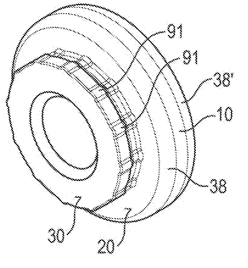
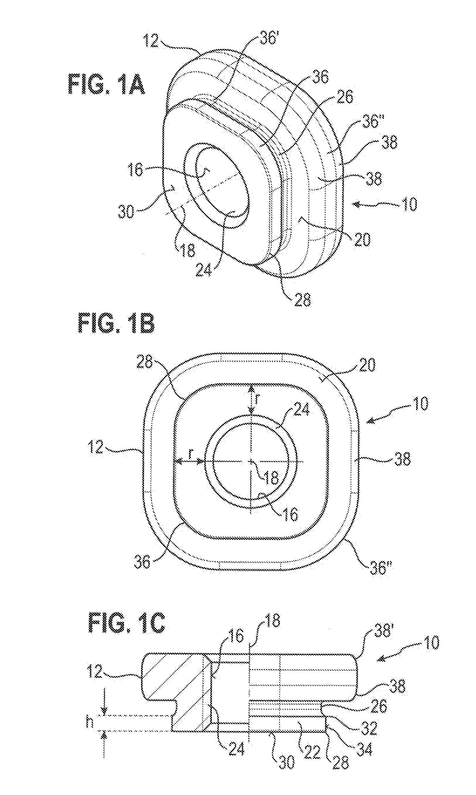
[0049]The FIGS. 1A to 1C show first of all a first embodiment of a self-piercing nut element 10 in accordance with the invention having a strength in the range between 700 and 900 MPa, in exceptional cases of up to 1250 MPa which is designed to be pressed into a sheet metal part, with the nut element having the following features:

[0050]A head part 14 forming a flange 12, a central bore 16 in the head part 14 which serves to accommodate a bolt element (not shown) and which has a central longitudinal axis 18, a sheet metal contact surface 20 formed in a plane standing at least substantially perpendicular to the central longitudinal axis 18 at the flange 12 and also a piercing section 22 extending away from the head part at the side of the sheet metal contact surface in the direction of the longitudinal axis. The bolt element can for example be a threaded bolt, whereby the nut element 10 is provided here with a thread cylinder 24, i.e. the bore 16 is a threaded bore. However, it could ...


PUM


Abstract

A piercing nut element having a strength in the range between 700 and 900 MPa which is designed to be pressed into the sheet metal part. The nut element is characterized in that the self-piercing attachment of the nut element into a sheet metal part of higher strength, or into a sheet metal part with a thickness greater than 3.5 mm, the nut element is designed in such a way that the piercing section has a peripheral extending groove below the sheet metal contact surface and in that the piercing section has a piercing edge at its free end face with the piercing edge being spaced from the boundary of the groove adjacent to the piercing section by a peripheral surface having an axial height which corresponds to at least 30% and preferably to at least 50% of the sheet metal thickness, wherein the radial wall thickness of the piercing section in the region of its free end face from the outer side of the piercing section up to the nominal diameter of the thread corresponds to a thickness between 1.2 to 1.8 and preferably 1.5 times the intended sheet metal thickness.

Description

CROSS-REFERENCE TO RELATED APPLICATIONS[0001]This application claims priority of German Patent Application No. 10 2009 039 817.1, filed Sep. 2, 2009, the disclosure of which is expressly incorporated by reference herein in its entirety.FIELD OF THE INVENTION[0002]The present invention relates to a self-piercing nut element having a strength in the range between 700 and 900 MPa which is designed to be pressed into a sheet metal part with the nut element having the following features: a head part forming a flange, a central bore in the head part which is designed to receive a bolt clement and which has a central longitudinal axis, a sheet metal contact surface formed in a plane at least substantially perpendicular to the central longitudinal axis at the flange, as well as a piercing section extending away from the head part at the side of the sheet metal contact surface in the direction of the longitudinal axis. Furthermore, the present invention relates to a component assembly consis...

Claims


Application Information

Patent Timeline
Patent Type & Authority Applications(United States)
IPC IPC(8): F16B39/282
CPCF16B37/068B23P19/064F16B39/282
Inventor BABEJ, JIRISOWA, CHRISTIANHUMPERT, RICHARDVIETH, MICHAEL
Owner PROFIL VERBINDUNGSTECHN
Why Eureka
Try Eureka