
Apparatus, methods and systems for parallel power flow calculation and power system simulation

a technology of power system and method, applied in the field of apparatus, methods and systems for parallel power flow calculation and power system simulation, can solve the problems of large number of calculations required to perform the pf, and does not provide any information regarding the dynamics of the power system

Active Publication Date: 2011-09-01
SEAMAN ADEN +1
View PDF5 Cites 39 Cited by
  • Summary
  • Abstract
  • Description
  • Claims
  • Application Information

AI Technical Summary

Benefits of technology

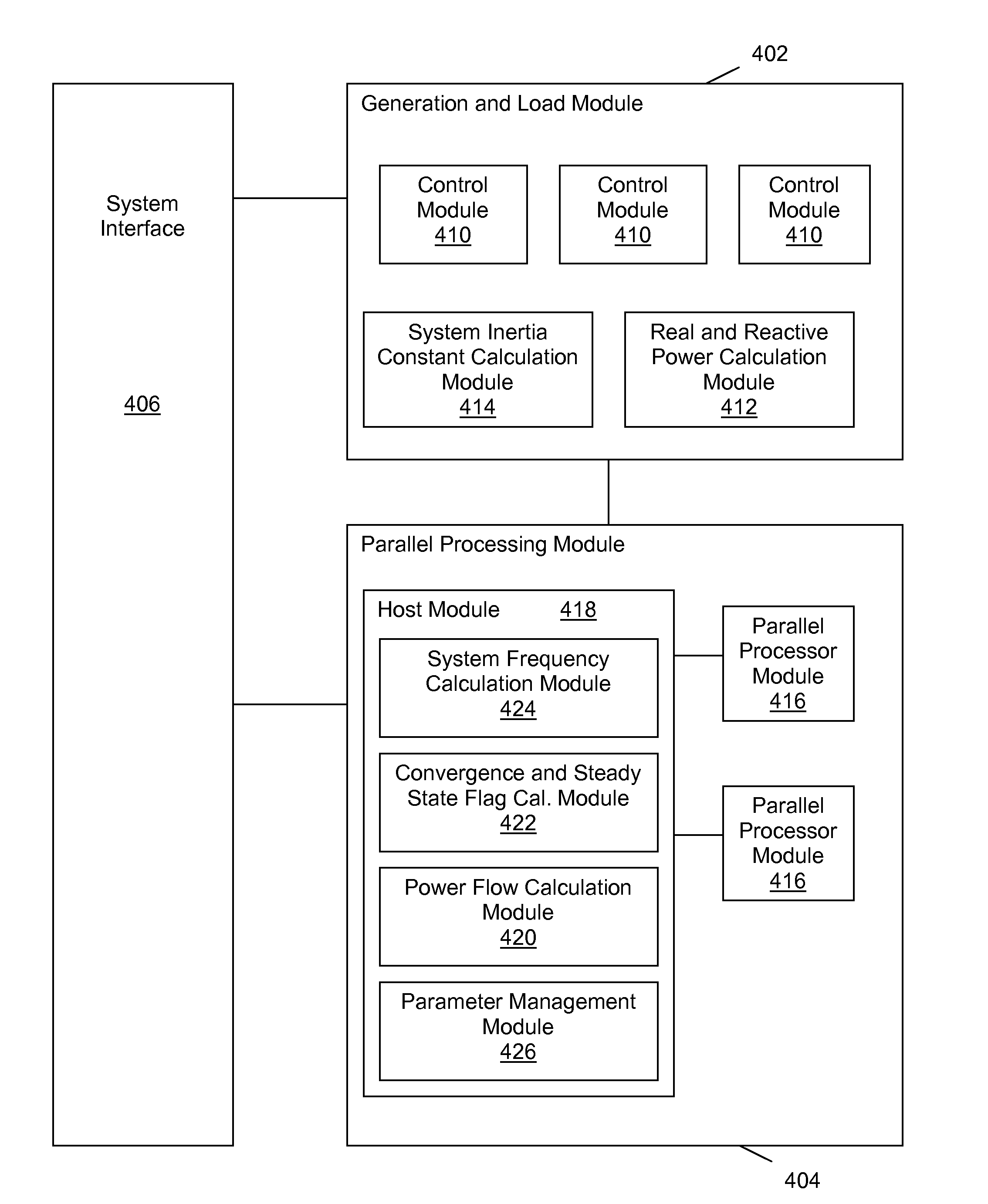
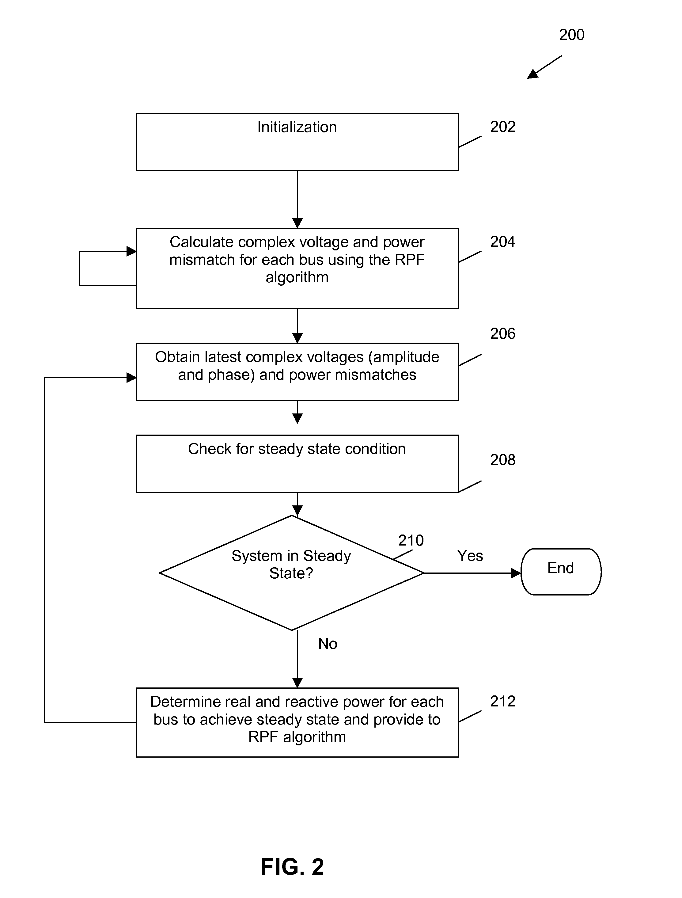
[0021]The system may also include (c) a system frequency calculation module for receiving the power mismatch for at least one bus and calculating a system frequency using the power mismatch of the at least one bus; and (d) a real and reactive power cal

Problems solved by technology

In its basic form it does not contain any time based information and does not provide any information regarding the dynamics of the power system.
Some obstacles to using the PF to implement a power system simulator include the large number of calculations required to performed the PF and the fact that the PF does not contain any information regarding the frequency of the system, a key indicator of power system state.

Method used


Image

  • Apparatus, methods and systems for parallel power flow calculation and power system simulation
  • Apparatus, methods and systems for parallel power flow calculation and power system simulation
  • Apparatus, methods and systems for parallel power flow calculation and power system simulation

Examples


Embodiment Construction

[0034]It will be appreciated that numerous specific details are set forth in order to provide a thorough understanding of the exemplary embodiments described herein. However, it will be understood by those of ordinary skill in the art that the embodiments described herein may be practiced without these specific details. In other instances, well-known methods, procedures and components have not been described in detail so as not to obscure the embodiments described herein. Furthermore, this description is not to be considered as limiting the scope of the embodiments described herein in any way, but rather as merely describing the implementation of the various embodiments described herein.

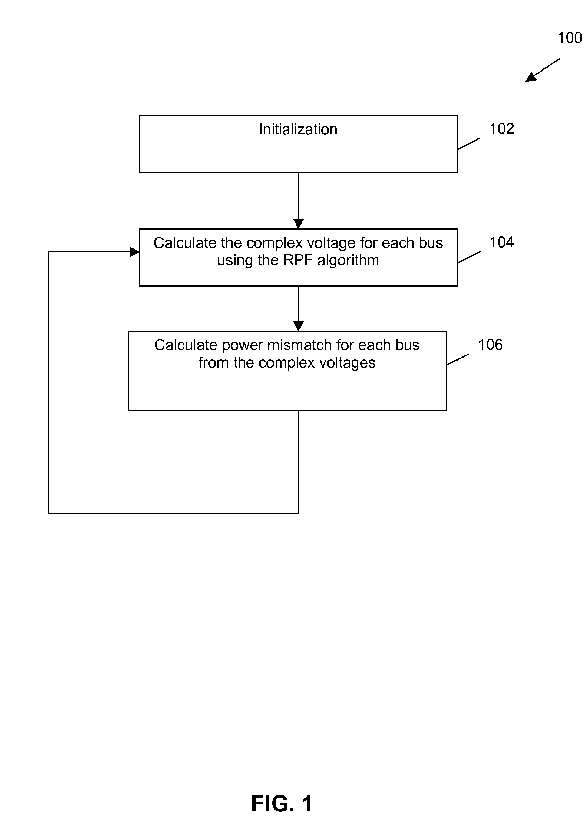
[0035]Some embodiments described herein relate to apparatus, systems and methods for computing a solution to the power flow equations using parallel processing. In one embodiment, the method implements a modified and simplified version of a standard power flow algorithm, referred to herein as the Raw...


PUM


Abstract

According to one aspect, an apparatus for computing a solution to a power flow problem for an electrical power system comprising a plurality of buses. The apparatus includes (a) at least one processor comprising a plurality of cores; and (b) memory coupled to the at least one processor for storing an admittance matrix for the power system, real power and reactive power for each bus, and an initial complex voltage for each bus; (c) wherein the at least one processor is configured to: (i) perform a Jacobi power flow calculation for each bus to determine the complex voltage for each bus, the Jacobi power flow calculation using the admittance matrix, the real power and reactive power for each bus, and the initial complex voltage for each bus as inputs, wherein at least two Jacobi power flow calculations are performed concurrently on the plurality of cores; (ii) calculate a power mismatch at each bus based on the complex voltages; and (iii) determine whether the Jacobi power flow calculations have converged based on the power mismatch and repeat (i) to (iii) if the Jacobi power flow calculations have not converged.

Description

RELATED APPLICATIONS[0001]This application claims the benefit of U.S. Provisional Patent Application Ser. No. 61 / 238,912 filed Sep. 1, 2009, the entire contents of which are incorporated by reference herein for all purposes.FIELD[0002]Embodiments described herein relate to apparatus, methods and systems for computing a solution to the power flow (load flow) problem and dynamically simulating a power system. In particular, the embodiments described herein relate to apparatus, methods and systems for computing a solution to the power flow problem and dynamically simulating a power system using parallel processing.INTRODUCTION[0003]Power system simulators, state estimators and economic optimal power flow calculators are core to the reliability of modern electricity systems and are used to plan, simulate, predict and control the state of every major electricity jurisdiction. They are also often used to perform desktop studies and analyses of theoretical systems. The prevalent operationa...

Claims


Application Information

Patent Timeline
IPC IPC(8): G06F9/455
CPCH02J3/00H02J2003/007G06F2217/78Y02E60/76G06F17/5009Y04S40/22H02J2203/20Y02B70/3225Y02E60/00Y04S20/222Y04S40/20G06F30/20G06F2119/06
Inventor SEAMAN, ADENROMANIUK, OLIVER
Owner SEAMAN ADEN
Learn More