Strapping machine

Active Publication Date: 2011-09-08
TEKPAK +1
View PDF2 Cites 5 Cited by
  • Summary
  • Abstract
  • Description
  • Claims
  • Application Information

AI Technical Summary

Benefits of technology

[0010]The object of the present invention is to provide a strapping machine. In which, the vertical moving distances of the access guiding potion and the exit guiding portion can be adjusted independently. Plus, it can save the waiting time. Therefore, this invent

Problems solved by technology

However, the traditional longitudinal strapping machine 80 still contains the following problems and disadvantages.
[1] It cannot make any adjustment depending on the height of the object.
But, it cannot make any adjustment depending on th

Method used


Image

  • Strapping machine
  • Strapping machine
  • Strapping machine

Examples


Embodiment Construction

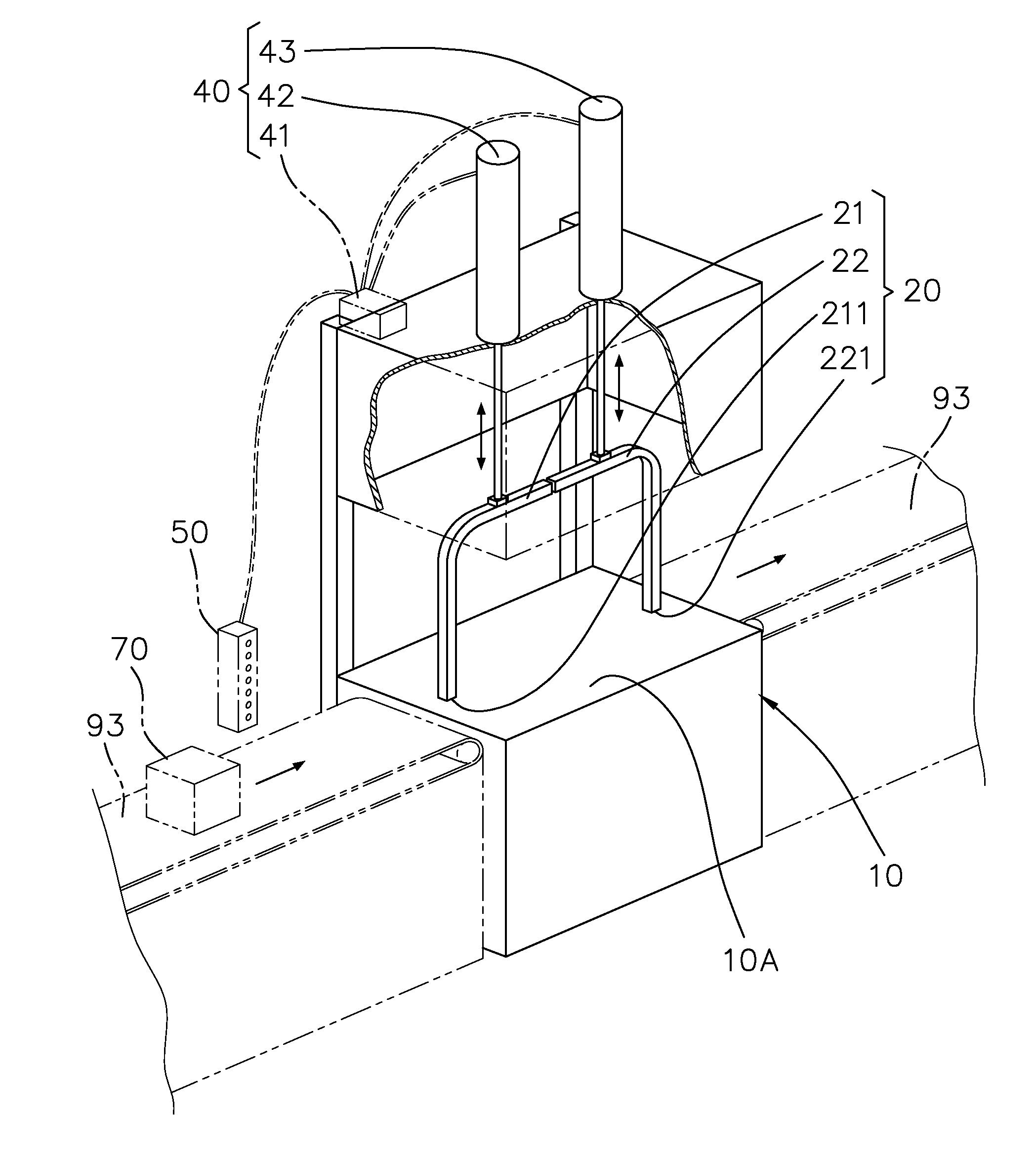
[0034]Referring to FIGS. 7, 8 and 9, the present invention is a strapping machine. It comprises a machine body 10, a strap chute 20, a strap supplying device 30, and a controlling device 40.

[0035]With regard to the machine body 10, it has a working surface 10A, a first hole 11, and a second hole 12.

[0036]The strap chute 20 includes an access guiding portion 21 and an exit guiding portion 22. The access guiding portion 21 has an access hole 211 which is corresponding to the first hole 11. The exit guiding portion 22 has an exit hole 221 which is corresponding to the second hole 12.

[0037]Concerning the strap supplying device 30, it can supply a strap 100 and can perform a strapping work. The strap 100 is supplied into the strap chute 20 via the first hole 11 and the access hole 211 and then is guided out via the exit hole 221 and the second hole 12. After which, the strap 100 is back to the strap supplying device 30 for performing a strapping movement. The strap supplying device 30 at...


PUM


Abstract

A strapping machine includes a machine body, a strap chute, a strap supplying device, and a controlling device. The machine body has a working surface. The strap chute includes an access guiding portion and an exit guiding portion. The controlling device can control the access guiding portion and the exit guiding portion moving to suitable heights independently. So, an object to can be moved in for a strapping work and then be moved out. Hence, the vertical moving distances of the access guiding potion and the exit guiding portion can be adjusted independently. In addition, it can save the waiting time.

Description

BACKGROUND OF THE INVENTION[0001]1. Field of the Invention[0002]The present invention relates to a strapping machine. Particularly, it relates to a strapping machine having an access guiding potion and an exit guiding portion that can be moved independently. The vertical moving distances of the access guiding potion and the exit guiding portion can be adjusted independently. In addition, it can save the waiting time.[0003]2. Description of the Prior Art[0004]Referring to FIG. 1, it shows the process of a conventional cross-strapping work. First, the object 70 (to be strapped) is moved by a conveyor system 93 to a conventional first strapping machine 91 (from a first position P1 to a second position P2). Then, it performs a first strapping work (or called lateral strapping). After which, this object 70 is moved to a third position P3. At this moment, the angle θ between the strap 100 on the object 70 and the moving direction is 90 degrees. A worker 71 has to rotate the object 70 nine...

Claims


Application Information

Patent Timeline
IPC IPC(8): B65B13/18
CPCB65B13/14
Inventor LIU, CHIN-CHANGSU, CHI-JAN
Owner TEKPAK
Why Eureka
Try Eureka