Methods, systems and devices for non-invasive ventilation including a non-sealing ventilation interface with an entrainment port and/or pressure feature

a non-invasive ventilation and interface technology, applied in the field of ventilation therapy, can solve the problems of not being able to mechanically help, consuming a significant amount of oxygen, and burdening the patient,

Active Publication Date: 2011-09-08
BREATHE TECHNOLOGIES INC
View PDF108 Cites 86 Cited by
  • Summary
  • Abstract
  • Description
  • Claims
  • Application Information

AI Technical Summary

Benefits of technology

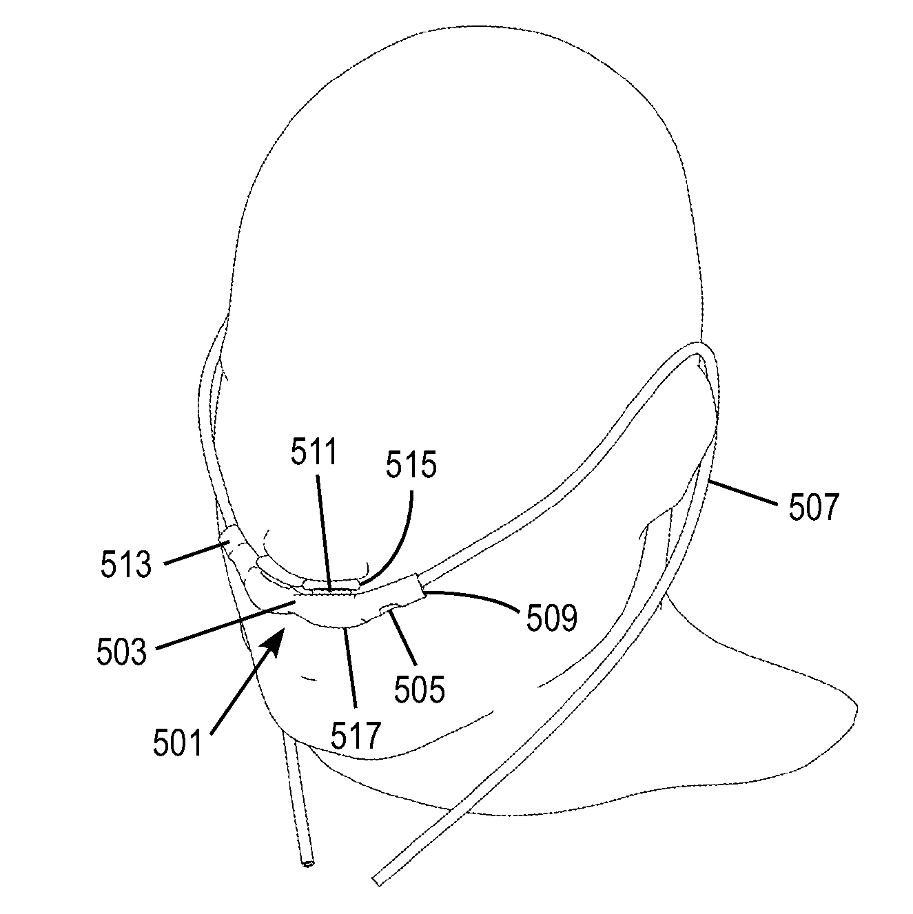
[0019]The systems and methods of the present invention may also include that the gas flow path includes a length between the nozzle and distal end allowing the velocity profile exiting the jet to merge with the walls of the gas flow path, and develop a positive pressure at a location proximal to the distal end and outside the nose. The minimum cross section of the gas flow path may be greater than or equal to the cross sectional area of the entrainment aperture. The entrainment aperture may be positioned in the tubular body at the anterior side of the tubular body, to entrain airflow into the aperture from in front of the face, and to direct exhaled gas flowing out of the aperture away from the face. The tubular body may include a sound reducing feature selected from the group of: a secondary port near the distal end, a nozzle position that is off-centered from the centerline axis of the tubular body, a nozzle angle that directs gas into the wall of the tubular body. The tubular body may include an internal volume of less than 0.40 cubic inches. The tubular body may include a gas flow resistance of less than 4 cmH2O pressure at 60 lpm gas flow. The pressure sensing port may be positioned in the positive pressure area of the tubular body. A left and a right tubular body may be provided, wherein each tubular body includes a pressure sensing port. An entrainment pressure sensing port may be located near the entrainment aperture, and a pressure sensing port may be located near the distal end.
[0020]Embodiments of the present invention may include a method of delivering a therapeutic level of gas to a patient wherein a delivered amount of gas increases pressure in an oropharyngeal airway to a pressure level able to reduce an obstructive sleep apnea airway obstruction, the method including: providing a nasal interface that does not impede the patient from breathing ambient air directly through the nasal interface, wherein the nasal interface includes: a jet nozzle in the nasal interface at a proximal end of the nasal interface substantially lateral to a nose; and an entrainment port in the nasal interface substantially between the jet nozzle and a distal end of the nasal interface; a ventilator and a gas delivery circuit, wherein the ventilator is in fluid communication with the jet nozzle via the gas delivery circuit; and delivering gas from the jet nozzle into the nasal interface with a velocity that creates a negative pressure area inside the nasal interface at the location of the entrainment port, at a distance from the distal end of the nasal interface, wherein the nasal interface is adapted to create a positive pressure area between the negative pressure area and the distal end of the nasal interface, and wherein substantially all exhaled gas flows through the entrainment port and virtually none of the exhaled gas flows through the gas delivery circuit. Delivery of gas may be synchronized with breathing of a patient.

Problems solved by technology

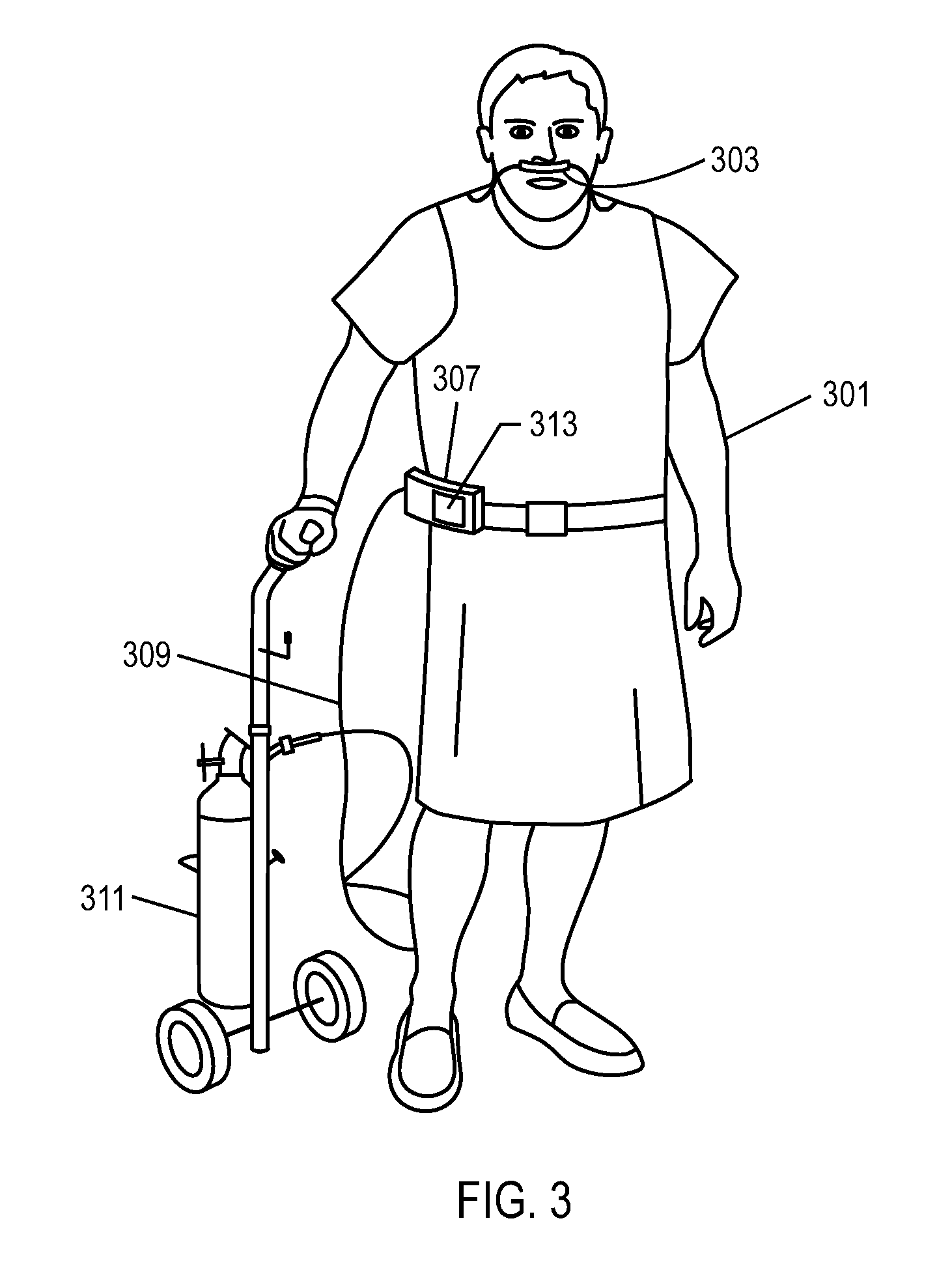
There is a need for a minimally obtrusive nasal mask and ventilation system that delivers mechanical ventilatory support or positive airway pressure, and which unencumbers the patient.
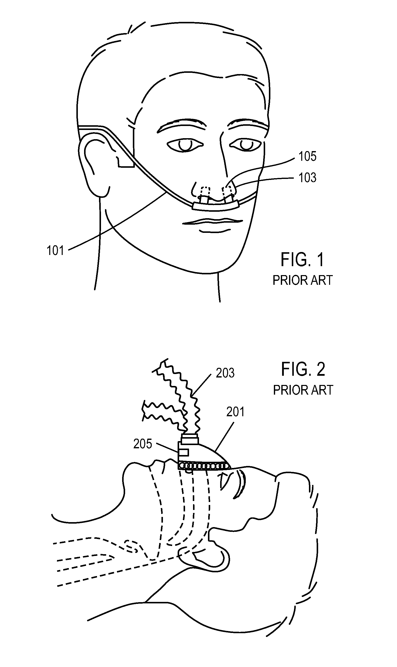
For example, some nasal mask oxygen therapy systems have been developed for the purpose of delivering mixtures of air and oxygen by entraining air into the mask, however these are not considered ventilation therapy or respiratory support, because they do not mechanically help in the work of breathing.
These systems are inefficient in that they consume a significant quantity of oxygen, rendering them non-mobile systems and encumbering the patient.
While helpful in supporting the work of breathing, the patient interfaces used for MV are obtrusive and / or invasive to the user, and MV does not facilitate mobility or activities of daily living, therefore encumbers that patient and is a drawback to many potential users.
However, the patient cannot use their upper airway because the interface makes an external seal against the nose and / or mouth, and in addition the system is not mobile, the combination of which does not enable activities of daily living.

Method used


Image

  • Methods, systems and devices for non-invasive ventilation including a non-sealing ventilation interface with an entrainment port and/or pressure feature
  • Methods, systems and devices for non-invasive ventilation including a non-sealing ventilation interface with an entrainment port and/or pressure feature
  • Methods, systems and devices for non-invasive ventilation including a non-sealing ventilation interface with an entrainment port and/or pressure feature

Examples


Embodiment Construction

ioning cushion.

[0057]FIG. 31 is a schematic view of an optional embodiment in which the ventilation gas is delivered to one side of the mask, with other features including a snap fit nasal cushion and a flex joint in the mask between the cushions.

[0058]FIG. 32 graphically shows how the patient's work of breathing may be beneficially affected by the invention when the invention is used for lung disease or neuromuscular disease applications.

[0059]FIG. 33 graphically shows lung volume on the x-axis and lung pressure on the y-axis to illustrate how the lung volumes achieved with NIOV on a lung simulator bench model in comparison to conventional ventilation.

[0060]FIG. 34 graphically illustrates the lung volumes achieved with NIOV in comparison to oxygen therapy, using the lung simulator bench model.

[0061]FIG. 35A graphically shows a square waveform gas delivery pressure, according to one embodiment.

[0062]FIG. 35B graphically shows the volume delivery of FIG. 35A.

[0063]FIG. 35C graphicall...


PUM


Abstract

Systems and methods may include a gas source, a gas delivery circuit, and a nasal interface allowing breathing ambient air through the nasal interface. A gas flow path through the nasal interface may have a distal gas flow path opening. A nozzle may be associated with a proximal end of the nasal interface a distance from the distal end gas flow path opening. At least a portion of an entrainment port may be between the nozzle and the distal end gas flow opening. The nozzle may deliver gas into the nasal interface to create a negative pressure area in the gas flow path at the entrainment port. The nasal interface and the nozzle may create a positive pressure area between the entrainment port and the distal end gas flow path opening. Gas from the gas delivery source and air entrained through the entrainment port may increase airway pressure or lung pressure or provide ventilatory support.

Description

CROSS-REFERENCE TO RELATED APPLICATIONS[0001]This application claims priority to U.S. Provisional Patent Application No. 61 / 239,728, filed Sep. 3, 2009, U.S. Provisional Patent Application No. 61 / 255,760, filed Oct. 28, 2009, U.S. Provisional Patent Application No. 61 / 294,363, filed Jan. 12, 2010, and U.S. Provisional Patent Application No. 61 / 306,370, filed Feb. 19, 2010; the contents of which are incorporated by reference herein in their entireties. This application also claims priority to U.S. Non-Provisional patent application Ser. No. 12 / 753,846, filed Apr. 2, 2010, PCT Patent Application No. PCT / US2010 / 029871, filed Apr. 2, 2010, U.S. Non-Provisional patent application Ser. No. 12 / 753,851, filed Apr. 2, 2010, PCT Patent Application No. PCT / US2010 / 029873, filed Apr. 2, 2010, U.S. Non-Provisional patent application Ser. No. 12 / 753,853, filed Apr. 2, 2010, U.S. Non-Provisional patent application Ser. No. 12 / 753,854, filed Apr. 2, 2010, PCT Patent Application No. PCT / US2010 / 029874...

Claims


Application Information

Patent Timeline
Patent Type & Authority Applications(United States)
IPC IPC(8): A61M16/00
CPCA61M16/00A61M16/1045A61M16/16A61M2016/0024A61M2016/0027A61M2016/1025A61M2205/3561A61M2205/42A61M2230/42A61M2230/432A61M2230/63A61M16/0672A61M16/0677A61M16/127A61M16/161A61M16/0063A61M16/0833A61M16/085A61M16/0858A61M2205/0216A61M2205/0238A61M16/0605A61M16/0051A61M2202/0208A61M2202/03A61M16/024A61M2202/0007
Inventor ALLUM, TODDAGUIRRE, JOEYCIPOLLONE, JOSEPHEGHBAL, DARIUSKAPUST, GREGORYWONDKA, ANTHONY D.
Owner BREATHE TECHNOLOGIES INC
Why Eureka
Try Eureka