Pressure sensor, pressure-differential flow rate meter, and flow rate controller

Active Publication Date: 2011-09-08
SURPASS IND
View PDF24 Cites 16 Cited by
  • Summary
  • Abstract
  • Description
  • Claims
  • Application Information

AI Technical Summary

Benefits of technology

[0011]The present invention has been conceived in light of the above-described circumstances, and an object thereof is to provide a pressure sensor that is capable of easily and completely displacing liquid by w

Problems solved by technology

That is, when the fluid to be flowed in the piping flow path is changed, any residue of the previously used fluid will cause a loss of cleanness; therefore, it is necessary to perform complete displacement by washing until

Method used


Image

  • Pressure sensor, pressure-differential flow rate meter, and flow rate controller
  • Pressure sensor, pressure-differential flow rate meter, and flow rate controller
  • Pressure sensor, pressure-differential flow rate meter, and flow rate controller

Examples


Example

[0037]An embodiment of a pressure sensor, a pressure-differential flow rate meter, and a flow rate controller according to the present invention will be described below on the basis of the drawings.

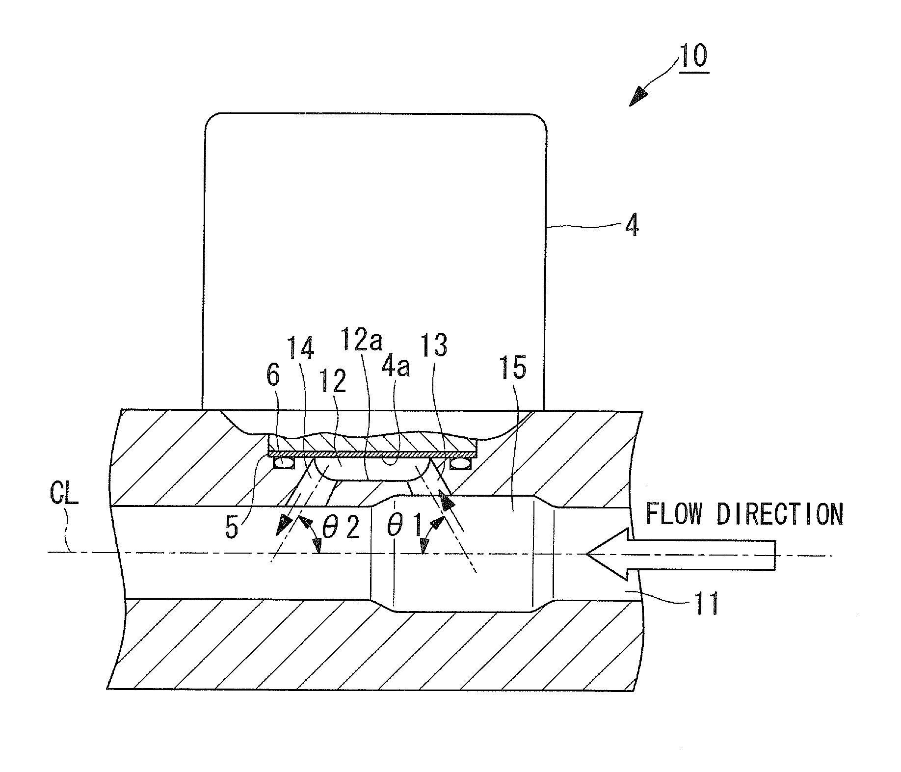
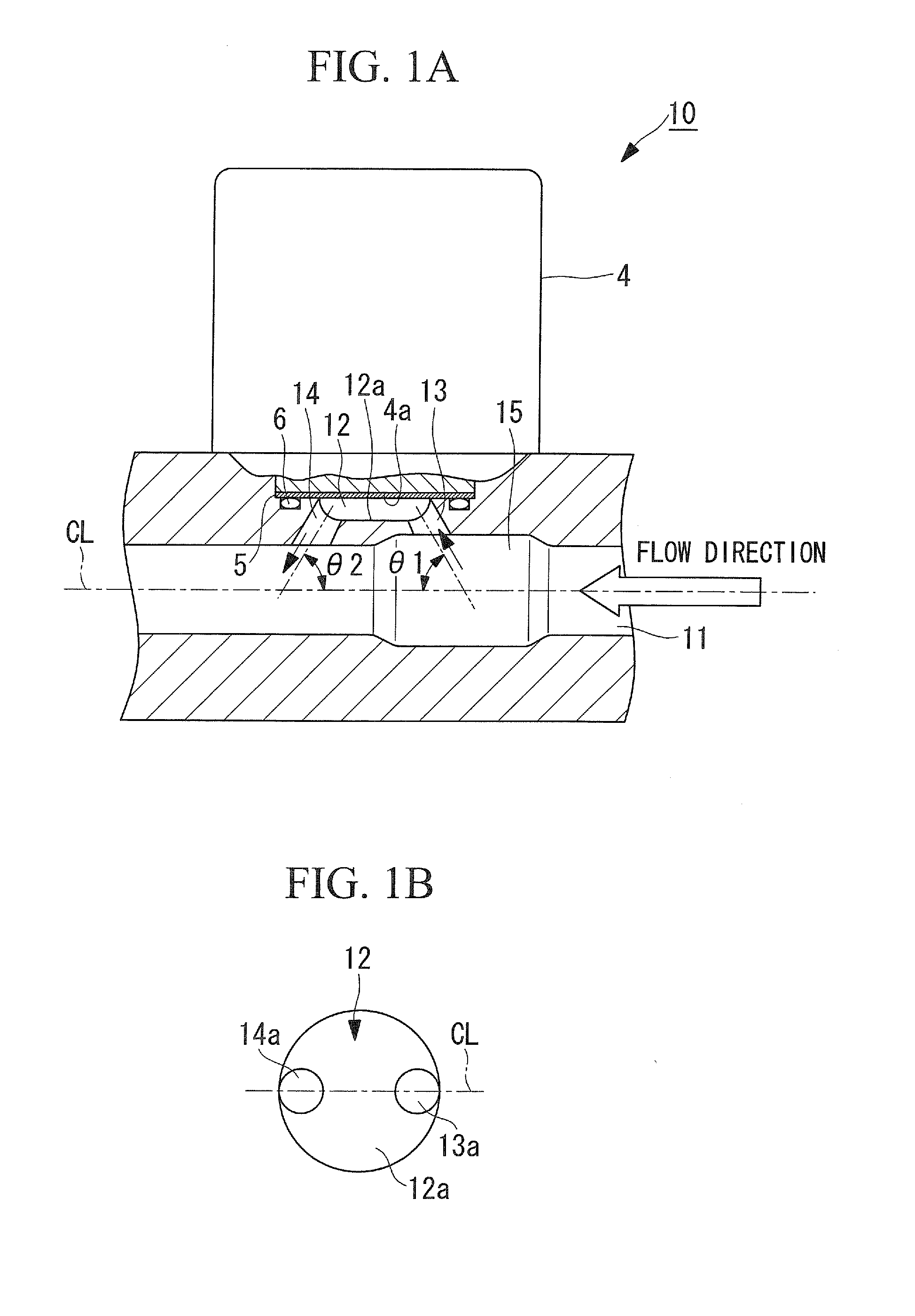
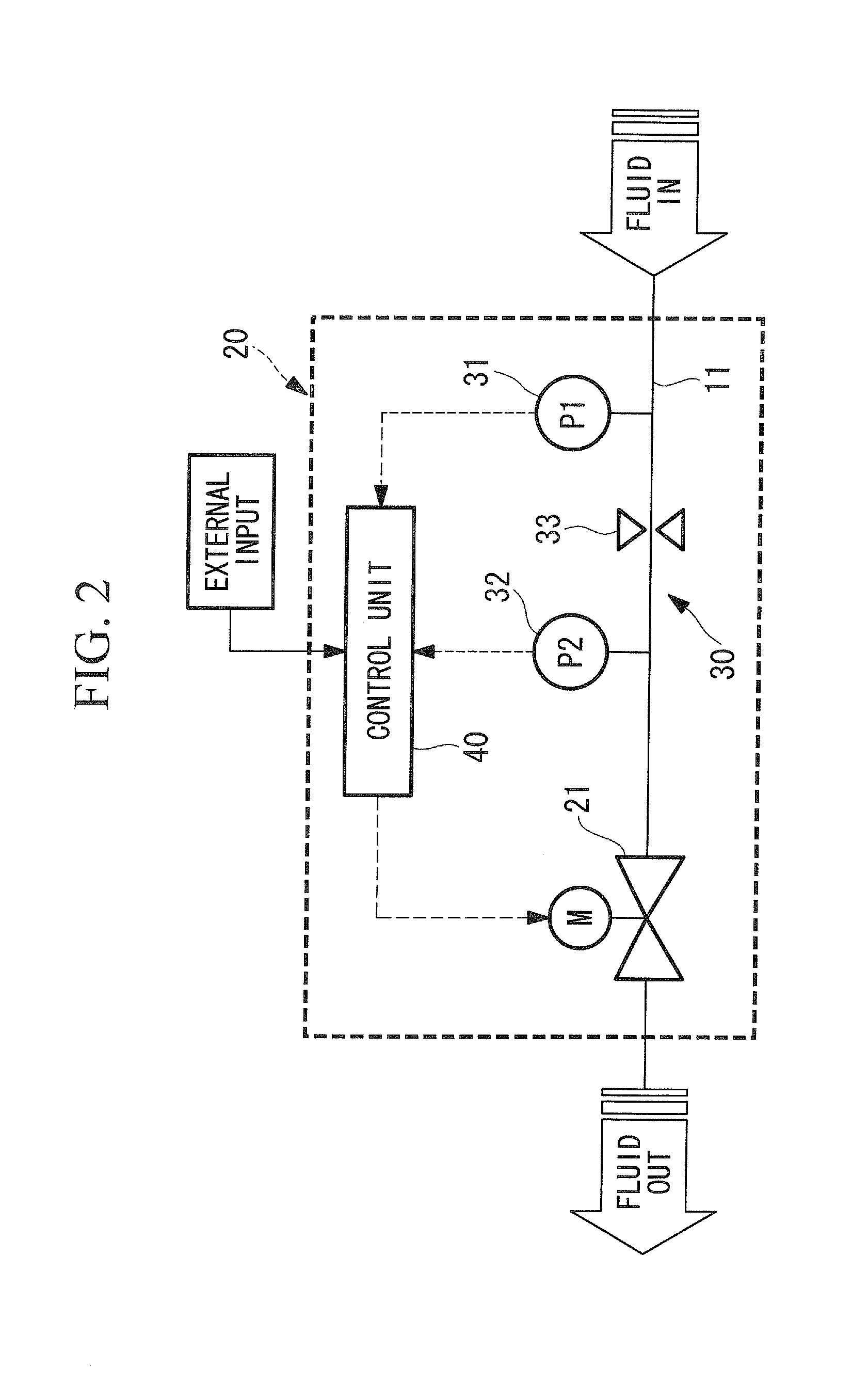
[0038]Pressure sensors 10 shown in FIG. 1A are installed in, for example, a straight-pipe portion of a main fluid flow path 11 formed of a piping system or the like, to detect the pressure of liquid that flows in the main fluid flow path 11. The pressure sensors 10 described above not only detect pressure by being installed at appropriate locations in the main fluid flow path 11 but are also installed, for example, in a flow rate controller 20 shown in FIG. 2 at an upstream side and a downstream side of an orifice 33, as pressure-difference-detecting pressure sensors 31 and 32 that constitute a pressure-differential flow rate meter 30.

[0039]The flow rate controller 20 is equipped with the pressure-differential flow rate meter 30 and a flow-rate adjusting valve 21, such as an electrically ...


PUM


Abstract

In a pressure sensor that detects the pressure of liquid flowing in a main fluid flow path, a pressure measuring unit is installed by providing a pressure measuring space at a position branching from a straight-pipe portion of the main fluid flow path, and, in addition, the main fluid flow path and the pressure measuring space are connected with an inlet pipe and an outlet pipe whose pipe diameters are smaller than the main fluid flow path.

Description

CROSS REFERENCE TO RELATED APPLICATIONS[0001]This application claims benefit of Japanese Application No. 2010-048903 filed in Japan on Mar. 5, 2010, the contents of which are hereby incorporated by its reference.BACKGROUND OF THE INVENTION[0002]1. Field of the Invention[0003]The present invention relates to a pressure sensor for detecting liquid pressure and also relates to a pressure-differential flow rate meter and a flow rate controller provided with this pressure sensor.[0004]2. Description of Related Art[0005]In the related art, there are known pressure-differential flow rate meters in which an orifice plate is installed somewhere in a piping flow path, and the flow rate of liquid is measured by measuring a pressure difference between an upstream side and a downstream side of the orifice plate. In addition, there is a known flow rate controller that adjusts the degree of opening of an electrically actuated valve or the like on the basis of the flow rate detected by a pressure-d...

Claims


Application Information

Patent Timeline
IPC IPC(8): F16K21/04G01F1/34
CPCG01F1/363G05D7/0635Y10T137/7762Y10T137/7837Y10T137/7761Y10T137/7759Y10T137/2087G01F1/34G01L19/06G05D7/00
Inventor IGARASHI, HIROKI
Owner SURPASS IND
Why Eureka
Try Eureka