Base insert device for paper bags

Inactive Publication Date: 2009-11-17
WINDMOELLER & HOELSCHER GMBH
View PDF22 Cites 6 Cited by
  • Summary
  • Abstract
  • Description
  • Claims
  • Application Information

AI Technical Summary

Benefits of technology

[0018]Application heads as set forth in the present invention are machine components, which are provided with glue outlet openings. These application heads usually contain a plurality of openings, are provided with glue supplying lines and also support a large number of valves. If a gluing station has only one application head, then the distance of the glue outlet openings in the direction perpendicular to the feed direction of the sheets or the tubular sections is decisive for the precision with which random glue profiles can be reproduced. However, due to the above-mentioned functions of an application head, this distance cannot be reduced randomly. If two or more application heads are provided whose relative positions in the direction perpendicular to the feed direction of the sheets or the tubular sections can be changed, then the possibility of the format-specific glue application improves considerably. In this connection, it is particularly important to supply the edges of the sheets and/or regions of the bases of the bags to be glued with sufficient quantities of glue.
[0019]It is advantageous to provide every application head with an application plate in which several glue outlet openings are arranged equidistantly in each case on one line in the direction perpendicular to the feed direction of the sheets and/or the folds of the bases. The application plates are arranged in such a way that the adjoining glue outlet openings of two different application heads can take up a distance that is smaller than the described equidistant distance. This is feasible if the application plates are arranged on the application heads such that they can be displaced easily. For example, in case of three application heads, the application plate can be attached centrally to the middle application head, whereas the application plates can be attached to the outer application heads in such a way that they c

Problems solved by technology

However, due to the above-mentioned functions of an app

Method used


Image

  • Base insert device for paper bags
  • Base insert device for paper bags
  • Base insert device for paper bags

Examples


Embodiment Construction

[0036]Further scope of applicability of the present invention will become apparent from the detailed description given hereinafter. However, it should be understood that the detailed description and specific examples, while indicating preferred embodiments of the invention, are given by way of illustration only, since various changes and modifications within the spirit and scope of the invention will become apparent to those skilled in the art from this detailed description.

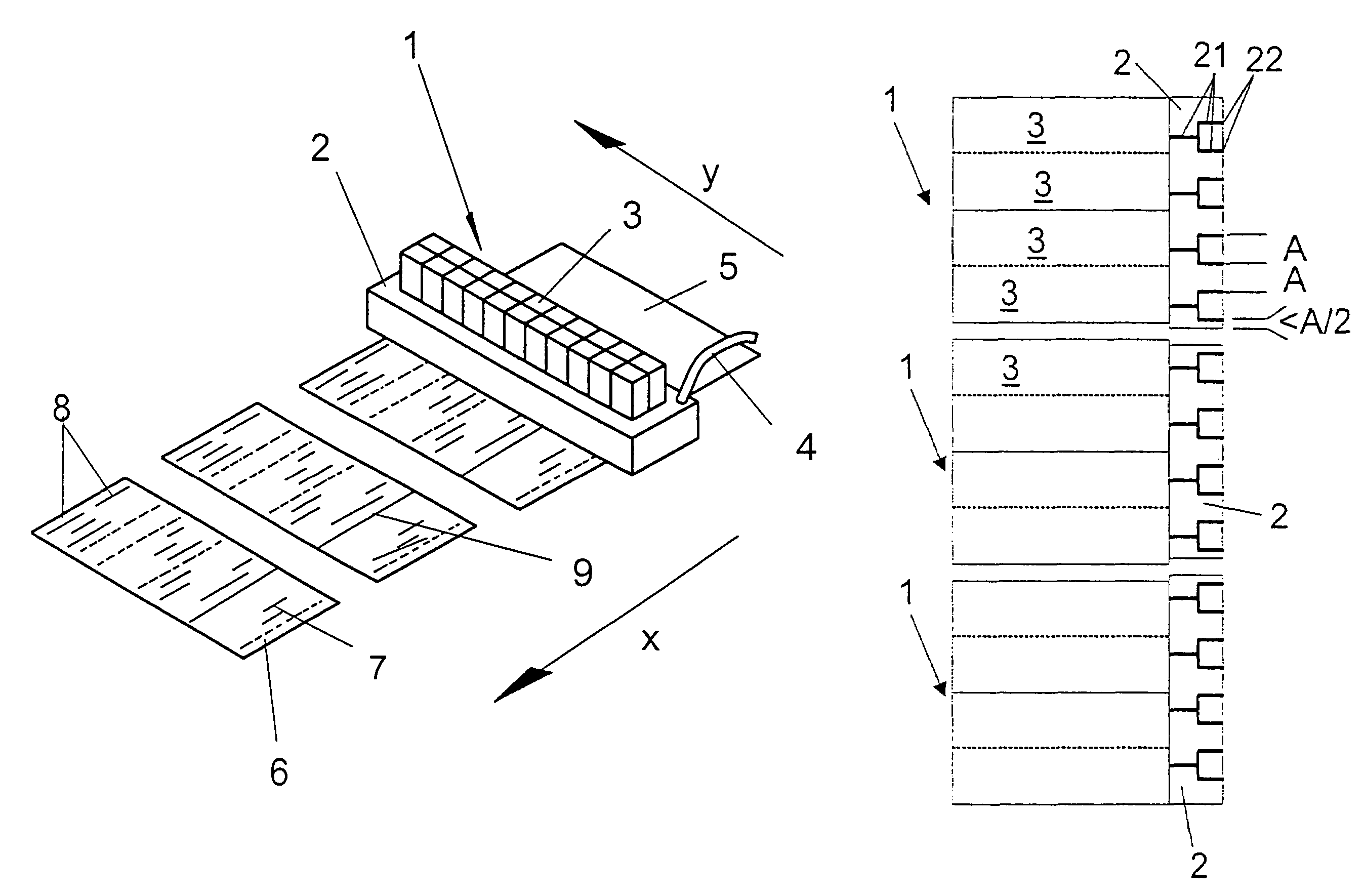
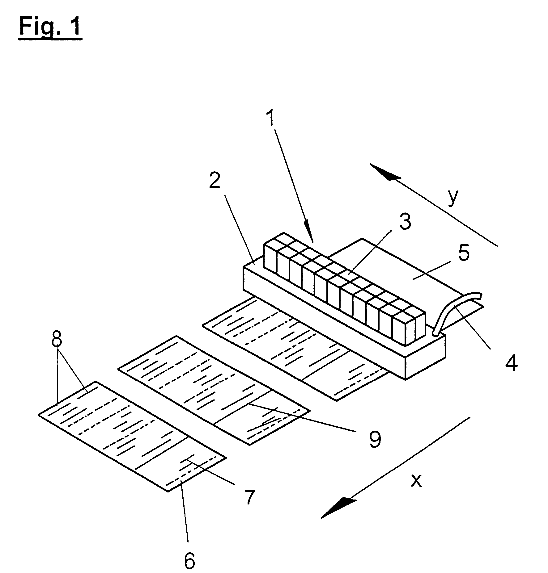
[0037]FIG. 1 illustrates an application head 1, as is used in a gluing station in the base insert device according to the present invention. This application head 1 is composed of an application plate 2, to which valves 3 are attached. The glue is supplied to the application head 1 via the glue supplying line 4. Unglued sheets 5 are supplied to the gluing station in direction x.

[0038]Every valve 3 is provided with one glue outlet opening or a group of glue outlet openings in the side of the application plate 2 th...


PUM


Abstract

The present invention relates to a base insert device for crossed base valve bags for the formation of crossed bases in paper bags, by means of folding devices which introduce folds at the ends of the tubular sections from which the bags are produced, with one or more gluing stations, which apply glue to the regions of the folds for gluing and/or the sheets (5) provided for gluing to the base, in the gluing stations and at least one pressing station in which the folded bases and the sheets (5) are brought into contact and glued.
The novelty of the present patent application is that at least one gluing station for the sheets and/or bases is provided, comprising glue outlet openings (22) which may be selectively supplied with glue, whereby the selection of the glue outlet openings (22) defines the format of the glue application (6, 7, 8, 9). Said glue outlet openings (22) are provided with at least two application heads (1) of which at least one application head (1) may be displaced in a direction (y) orthogonal to the feed direction of the sheets (5) and/or the folded bases such that as a result of the displacement, a relative movement of the two application heads (1) occurs.

Description

[0001]This is a nationalization of PCT / EP04 / 007298 filed Jul. 5, 2004 and published in German.BACKGROUND OF THE INVENTION[0002]1. Field of Invention[0003]The present invention relates to a base insert device for paper bags. The apparatus has folding devices, gluing stations that apply glue to the regions of the folds and / or to sheets provided for gluing to the base, and a pressing station in which the folded bases and the sheets are brought into contact and adhered to one another.[0004]2. Description of the Prior Art[0005]Devices of this type are used in the production of various types of bags. These bags include, for example, the so-called valve bags in which valve patches are usually inserted when manufacturing the bases of the bags. The bases are frequently designed as crossed bases as illustrated, for example in the patent applications DE 090 145 48 U1 and DE 3020043 A1. In order to provide the bases and the inserted valve patches with a lasting cohesion, parts of the bases are ...

Claims


Application Information

Patent Timeline
IPC IPC(8): B31B1/62B05C5/02B31B19/62B31B50/62
CPCB31B19/62B05C5/027B31B2219/6007B31B70/00B31B2160/10B31B70/62B31B70/85
Inventor DAHER, MARCOKOEHN, UWELAMKEMEYER, ANDREAS
Owner WINDMOELLER & HOELSCHER GMBH
Why Eureka
Try Eureka