

Optical biosensor using spr phenomenon
- Summary
- Abstract
- Description
- Claims
- Application Information
AI Technical Summary
Benefits of technology
Problems solved by technology
Method used
Image

Examples
embodiment
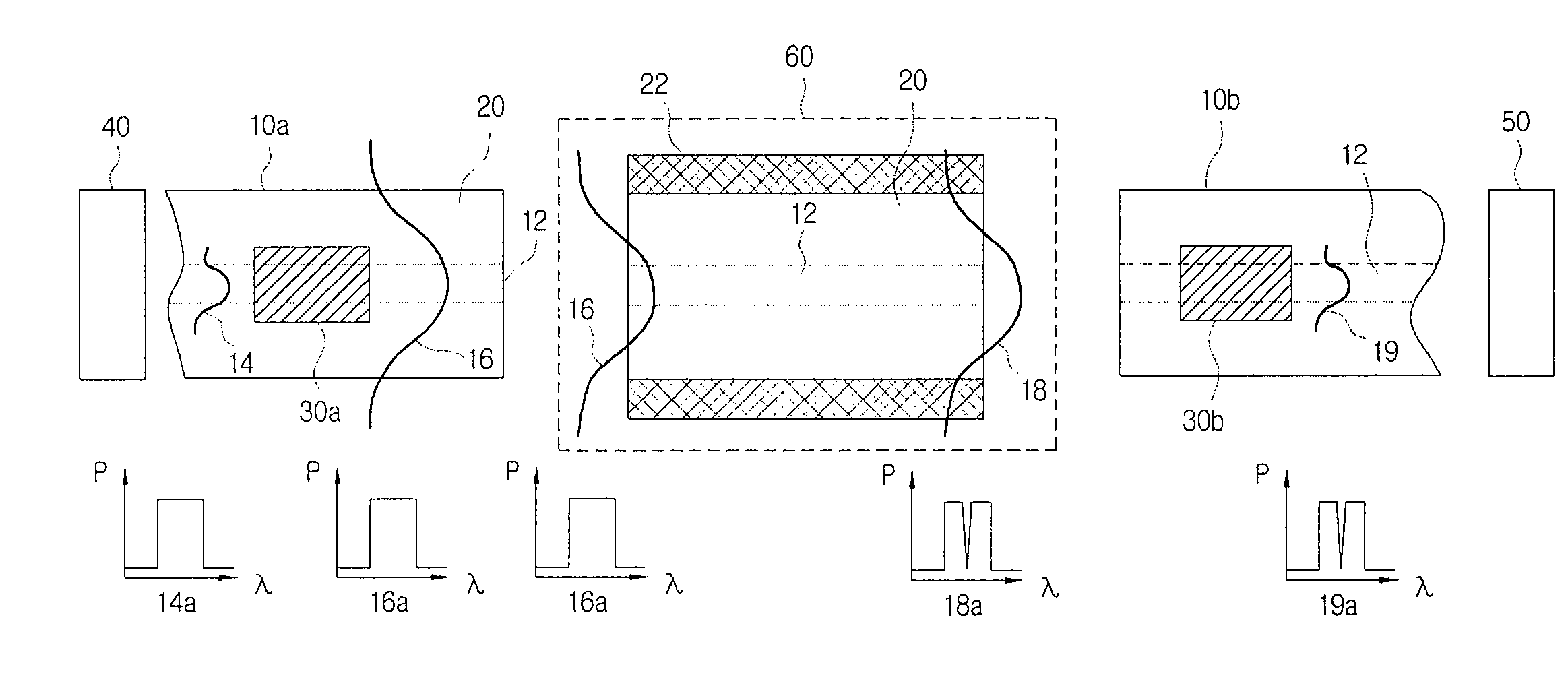
[0043]FIG. 4 is a view illustrating a construction of an optical biosensor using a SPR phenomenon according to an embodiment of the present invention, FIG. 5 is a view illustrating an optical spectrum of a cladding mode outputted from an optical sensing unit according to an embodiment of the present invention, and FIG. 6 is a graph illustrating the shifts of wavelength where the mode coupling between the cladding mode and the surface plasmon mode occurs, resulting in a substantial signal power drop, with respect to the density of bio-material (i.e., here, IgG concentration) according to an embodiment of the present invention.
[0044]With reference to FIG. 4, an optical sensor according to the present invention may include an input optical waveguide (i.e. an optical fiber or planar waveguide) 10a, an optical sensing unit 60, and an output optical waveguide 10b. Light 14 or an optical signal 14a, which has been emitted from an optical source 40 and has been inputted into the input optic...
PUM
 Abstract
Description
Claims
Application Information