Method of manufacturing a key top for a push-button switch

Inactive Publication Date: 2006-02-07
POLYMATECH CO LTD
View PDF8 Cites 19 Cited by
  • Summary
  • Abstract
  • Description
  • Claims
  • Application Information

AI Technical Summary

Benefits of technology

[0034]FIGS. 9A and 9B are explanatory views showing manufacturing steps of a key top for a push-button switch which is obtained in the course of creating the present invention, in which FIG. 9A is a partial sectional view showing a state where a h

Problems solved by technology

That is, when the above-described releasable sheet material is used, the metallic thin film layer can be readily detached from the sheet material so that bur

Method used


Image

  • Method of manufacturing a key top for a push-button switch
  • Method of manufacturing a key top for a push-button switch
  • Method of manufacturing a key top for a push-button switch

Examples


Example

EXAMPLE 1

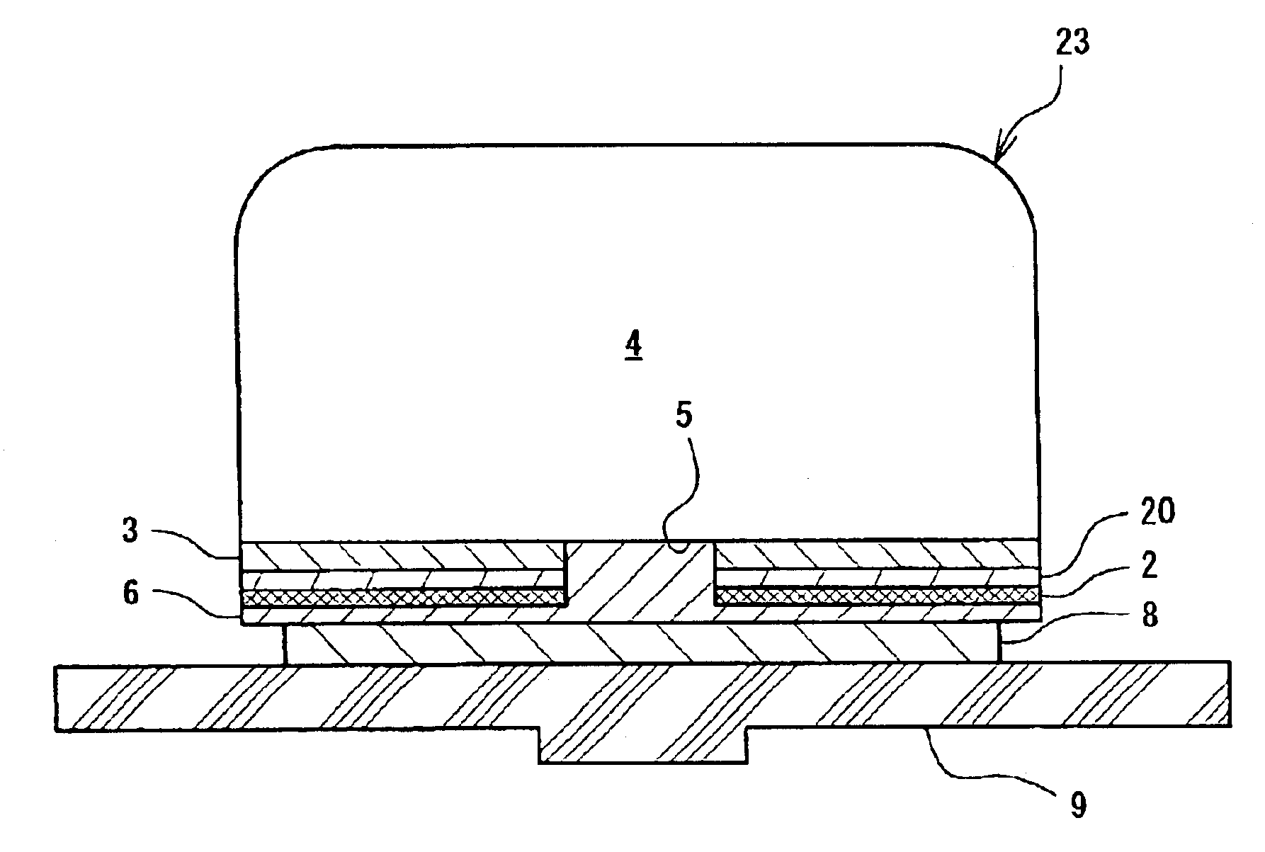
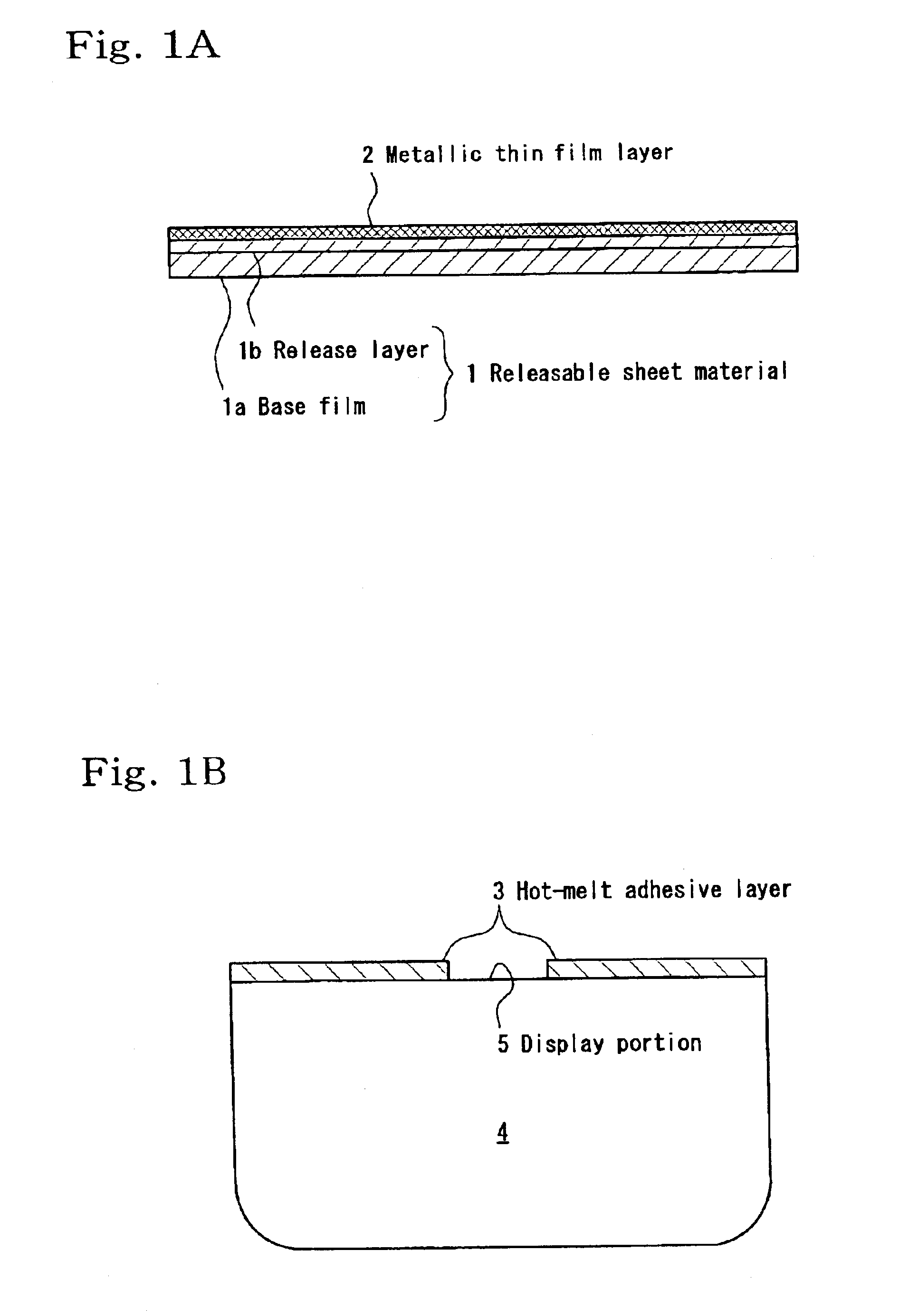
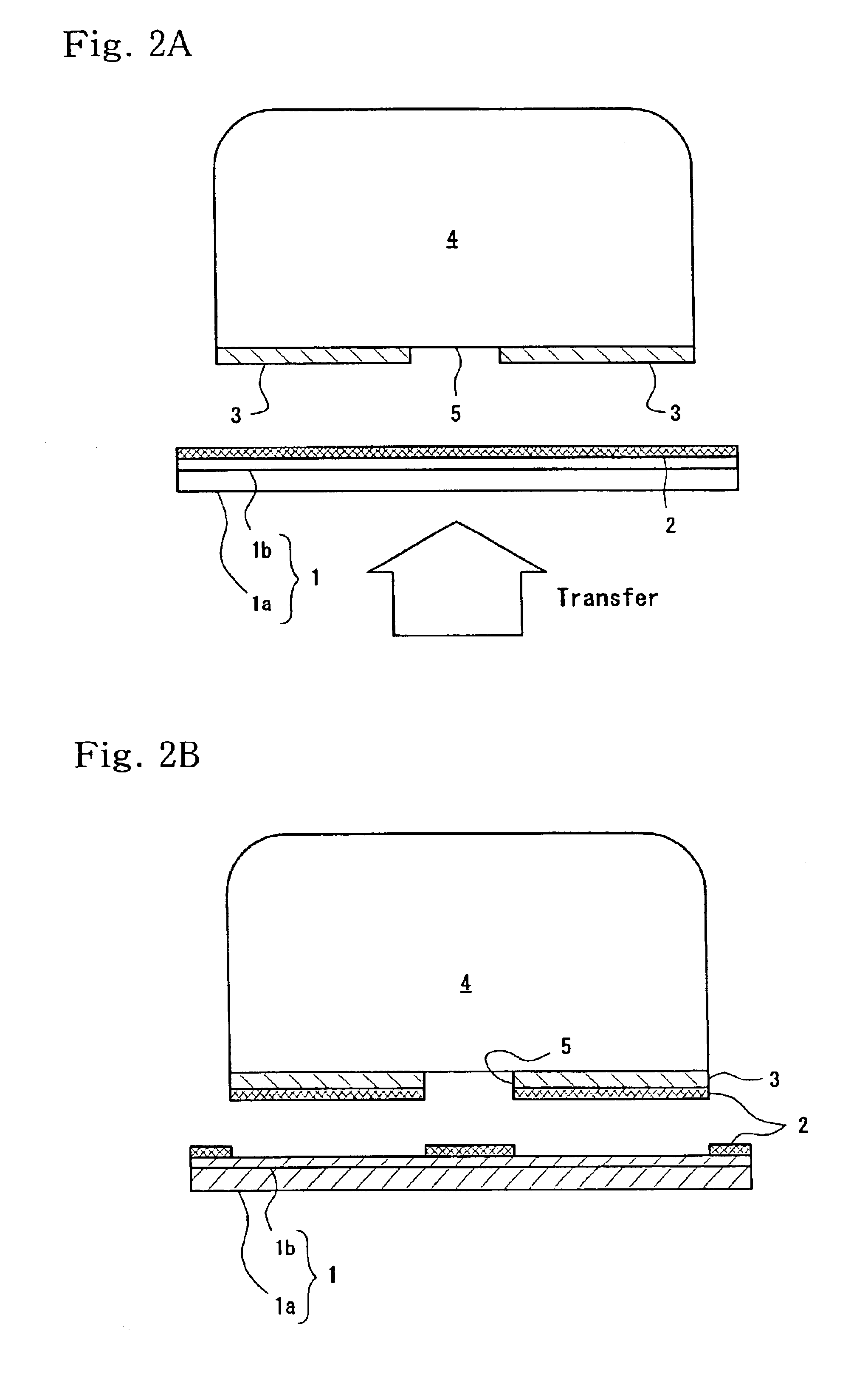
[0061]Example 1 of the invention corresponds to a method of manufacturing a push-button switch key top 7 shown in FIGS. 1A to 3B. That is, a release layer 1b is first formed on a polyester-based base film 1a having a thickness of 16 μm. Then, an aluminum thin film layer 2 is formed by vacuum deposition on the release layer 1b to have a layer thickness of 30 nm and a visible light transmission of 20% to 35% such that the aluminum thin film layer 2 has both a metal-like luster and illuminance (transparency) as a metallic thin film layer 2. Note that the visible light transmission in this example is measured by using a UV-visible spectrophotometer (UV-1600 manufactured by Shimadzu Corporation) and is a transmission read with respect to a wavelength (520 nm) of an LED that is generally used as a backlight light source of electronic equipment such as a mobile telephone. On the other hand, on the rear surface of a polycarbonate resin key top 4 that is formed by molding, a transpa...

Example

[0062]Example 2 of the invention corresponds to a method of manufacturing the push-button switch key top 7 shown in FIGS. 1A to 3B. That is, a release layer 1b is first formed on a polyester-based base film 1a having a thickness of 16 μm Then, an aluminum thin film layer 2 is formed by vacuum deposition on the release layer 1b so as to have a layer thickness of 200 nm and a visible light transmission of 0% so that the aluminum thin film layer 2 has both a metal-like luster and illuminance (transparency) as a metallic thin film layer 2. Note that the visible light transmission is the transmission obtained by the same measurement method as used in Example 1 described above. On the other hand, on the rear surface of a polycarbonate resin key top 4 that is formed by molding, a red transparent acrylic-based hot-melt adhesive is coated in a die-cut shape corresponding to a display portion 5 to form a hot-melt adhesive layer 3. Next, the aluminum thin film layer 2 is transferred onto the r...

Example

[0063]Example 3 of the invention corresponds to a method of manufacturing a push-button switch key top 14 shown in FIG. 4. That is, a release layer 1b is first formed on a polyester-based base film 1a having a thickness of 25 μm. Then, a chrome thin film layer 12 is formed by vacuum deposition on the release layer 1b so as to have a layer thickness of 20 nm and a visible light transmission of 18% to 37% such that the chrome thin film layer 12 has both a metal-like luster and illuminance (transparency) as a metallic thin film layer 12. Note that the visible light transmission is the transmission obtained by the same measurement method as used in Example 1 described above.

[0064]On the other hand, on a polycarbonate resin key top 4 that is formed by molding, a transparent acrylic-based hot-melt adhesive is coated in the same shape as a display portion 5 to form a hot-melt adhesive layer 11. Next, the chrome thin film layer 12 is transferred through the hot-melt adhesive layer 11 having...


PUM

PropertyMeasurementUnit
Fractionaaaaaaaaaa
Fractionaaaaaaaaaa
Thicknessaaaaaaaaaa

Abstract

A method of manufacturing a key top for a push-button switch according to the present invention includes forming a hot-melt adhesive layer on a resin key top so as to have a shape corresponding to a display portion for displaying a letter, symbol, or other indicia, and transferring a metallic thin film layer onto the hot-melt adhesive layer. Therefore, the metallic thin film layer is not damaged due to coating of the hot-melt adhesive layer, and positioning of the display portion is unnecessary. Further, when a transfer resin layer is formed on the metallic thin film layer, oxidation of the metallic thin film layer or damages thereto can be prevented.

Description

BACKGROUND OF THE INVENTIONCROSS REFERENCE TO RELATED DOCUMENTS[0001]This application claims priority to Japanese Patent Application Numbers: 2001-351130, filed on Nov. 16, 2001 and 2002-180232, filed on Jun. 20, 2002.[0002]1. Field of the Invention[0003]The present invention relates to a key top used for a push-button switch of communication devices such as a mobile telephone, an automobile telephone, or a remote controller, or for a push-button switch of various other electric / electronic devices, and to a method of manufacturing the key top.[0004]2. Description of the Related Art[0005]As a conventional cover member for a push-button switch used in a communication device, in particular a mobile communication device, such as a mobile telephone or an automobile telephone, there has been widely used a cover member for an illuminated push-button switch consisting of a transparent resin key top and a transparent elastic keypad. Of such cover members, those which tend to be particularly ...

Claims


Application Information

Patent Timeline
IPC IPC(8): H01H11/00H01H11/02H01H11/04H01H65/00H01H13/02H01H13/14H01H13/702
CPCH01H13/702H01H2209/0021H01H2219/03Y10T29/49105Y10T428/24752Y10T428/24802Y10T29/4998H01H2229/01
Inventor SHIMIZU, MASANORIKIKUCHI, KAZUO
Owner POLYMATECH CO LTD
Why Eureka
Try Eureka