Air / wind tunnel powered turbine, electric power recharging system

Inactive Publication Date: 2011-09-08
PROKOPICH BRENNAN MIKAEL
View PDF6 Cites 5 Cited by
  • Summary
  • Abstract
  • Description
  • Claims
  • Application Information

AI Technical Summary

Benefits of technology

[0009]It is a further object of the present invention to vastly reduce the operating costs that are typically associated with the use of an internal combustion engine by eliminating the need for expensive petroleum fuels.
[0010]It is a further object of the present invention to almost eliminate fuel emissions that are associated with the use of the internal combustion

Problems solved by technology

Thus, undesirable vehicle emissions associated with the use of petroleum or coal products continue to be a worldwide problem.
Over the years to this

Method used


Image

  • Air / wind tunnel powered turbine, electric power recharging system
  • Air / wind tunnel powered turbine, electric power recharging system
  • Air / wind tunnel powered turbine, electric power recharging system

Examples


Example

[0022]To make this description more clear, identical components having identical functions have been assigned with reference numerals.

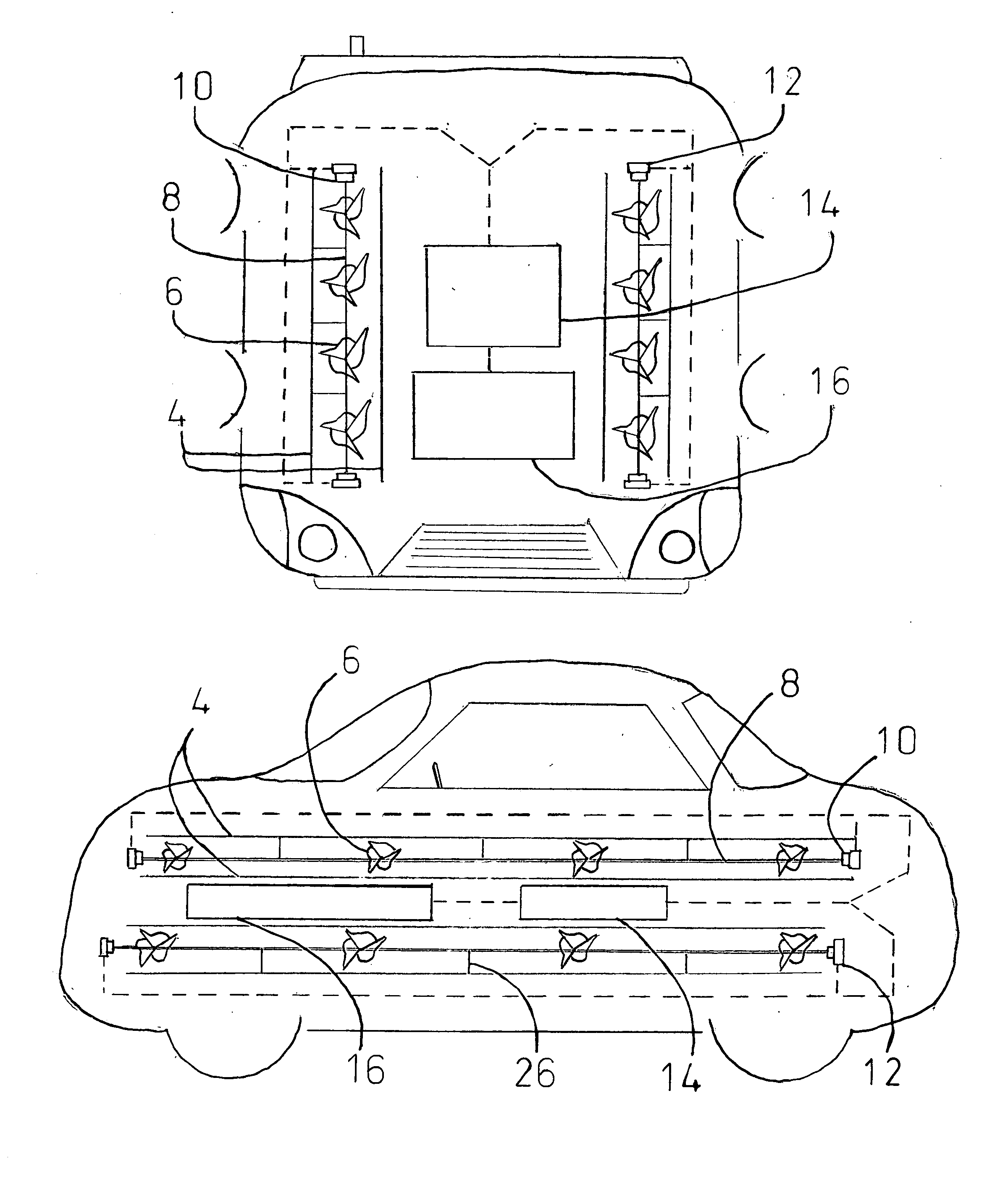
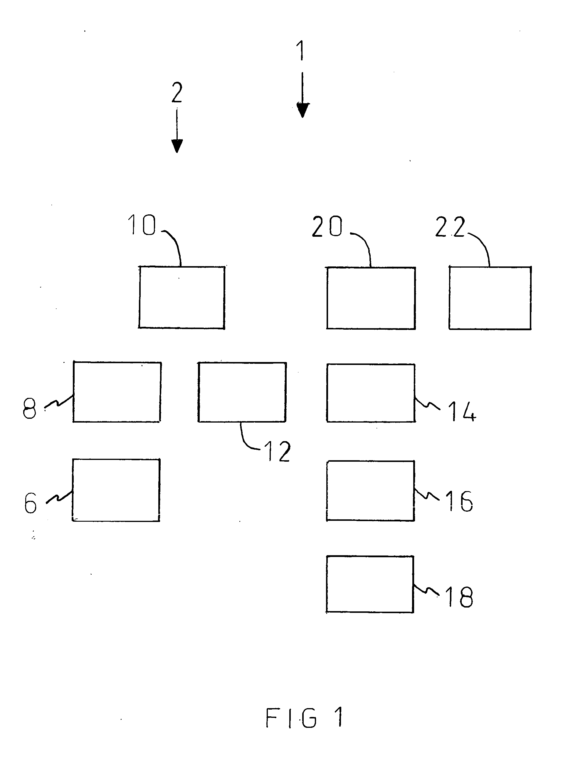
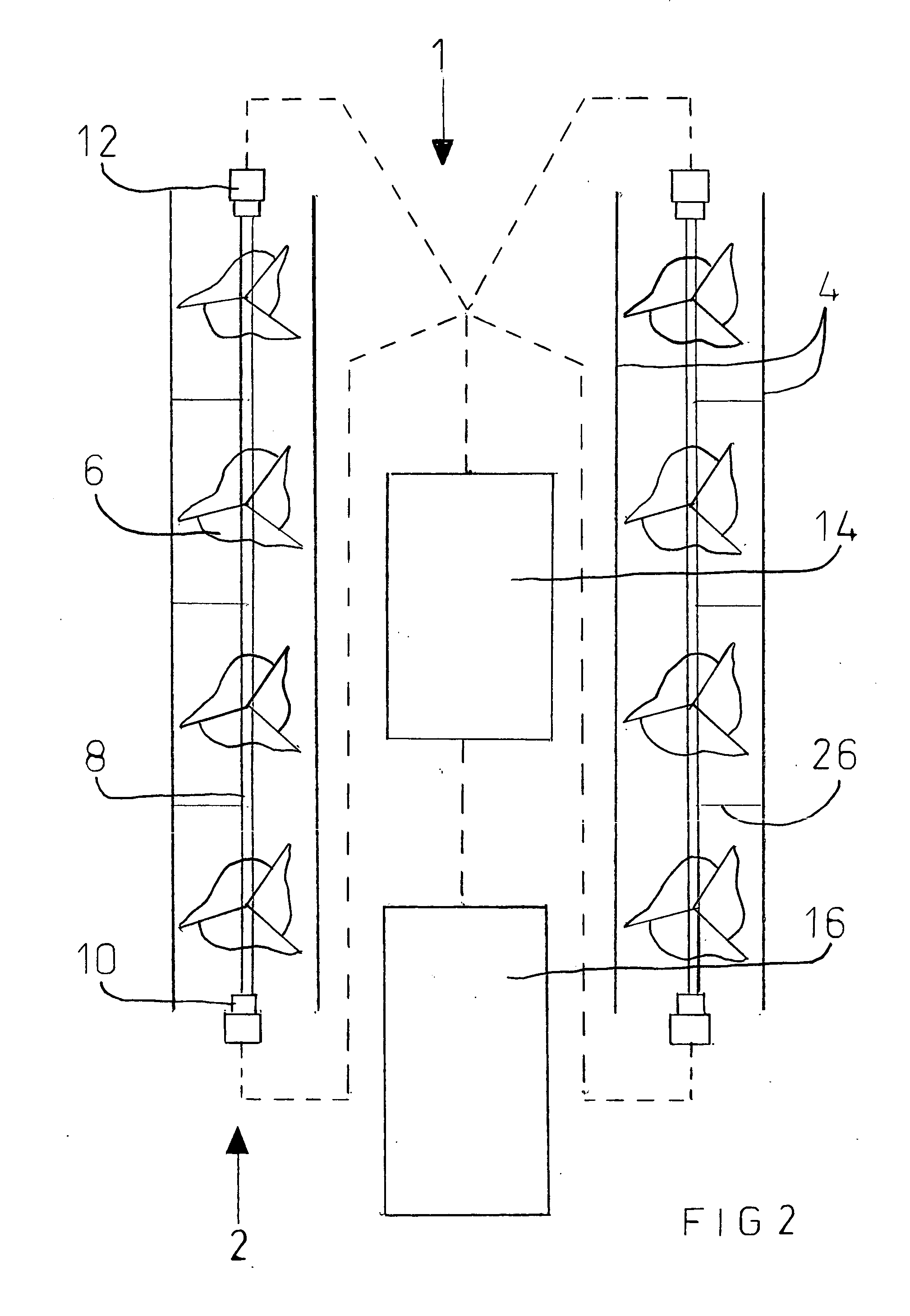
[0023]Refer to FIGS. 1-9 of the drawings illustrated therein is an air / wind tunnel power regeneration system which is designated #1 which is usable on a vehicle. The system designated #1 includes an air / wind tunnel turbine designated #2 which is uniquely constructed to be faced into the wind from the forward motion of a vehicle. Briefly the turbine includes at least one propeller designated #6 formed from a plurality of blades, a rotor shaft designated #8, and mounted stabilizers for the rotor shaft designated #26. Attached at each end of at least one rotor shaft is a gear system designated #10 which may or may not be attached at each end of at least one rotor shaft mounted to the vehicle, this runs through the air / wind tunnel designated #4 which is on or through the longitudinal axis of a vehicle.

[0024]As it is known in the art, an air / wind current c...


PUM


Abstract

The present invention provides an air/wind tunnel power system for a vehicle having an electrically operable drive system. The system includes at least one battery which is mounted within such vehicle and is connected to such drive system and at least one air/wind powered turbine which is mounted on such vehicle and is electrically coupled to the at least one battery. The air/wind powered turbine has a propeller fixed in a vertical plane and affixed to a horizontally disposed shaft running on a longitudinal axis of such vehicle through a tunnel all having an axis thereof disposed horizontally. A rotational movement of the propeller caused by an air current enables the at least one turbine to generate an electric energy which is stored in the at least one battery which is used by such drive system to move such vehicle in a direction of travel.

Description

CROSS REFERENCE TO RELATED APPLICATIONS[0001]This new Non Provisional application is a Continuation-In-Part (CIP) of the U.S. Provisional Patent Application No. 61 / 339,634 filed on Mar. 8, 2010 which had 1 year from the date filed. This application should have its filing date the same date as the end date of this particular application.FIELD OF THE INVENTION[0002]The present invention relates, in general, to a power system for vehicles and, more particularly, this invention relates to an air / wind power regeneration system for a vehicle which employs an air / wind operated turbine for generating electrical energy.BACKGROUND OF THE INVENTION[0003]As is generally known, vehicles for private, commercial and military either run on petroleum or coal products or on a combination of petroleum products and electric energy. The electric energy is generally used only on land vehicles wherein it can be generated of by rotating wheels. Thus, undesirable vehicle emissions associated with the use of...

Claims


Application Information

Patent Timeline
IPC IPC(8): F03D9/00H02K53/00
CPCY02E10/72H02K53/00F03D9/00Y02E10/728Y02E70/30B60K16/00F03D9/32F03D9/11F03D1/025Y02P70/50
Inventor PROKOPICH, BRENNAN MIKAEL
Owner PROKOPICH BRENNAN MIKAEL
Why Eureka
Try Eureka