Containerized continuous power system and method

a technology of continuous power generation and containerized power, applied in the integration of power network operation systems, emergency power supply arrangements, instruments, etc., can solve the problems of increasing the capacity of brick and mortar systems, increasing the cost of installation, and increasing the cost of maintenance and repair, etc., to achieve the effect of rapid deploymen

Inactive Publication Date: 2011-09-08
ACTIVE POWER INC
View PDF29 Cites 52 Cited by
  • Summary
  • Abstract
  • Description
  • Claims
  • Application Information

AI Technical Summary

Benefits of technology

[0007]Therefore, it is an object of this disclosure to provide a continuous power system that may be deployed quickly and at low cost to a variety of destinations. The containerized nature of the presently disclosed system may allow these advantages to be attained. The d...

Problems solved by technology

Traditionally, large-scale continuous power systems have required a heavy investment of time and capital to complete as a “brick and mortar” installation.
Further, such brick and mortar systems may tend to have a set output capacity that cannot easily be upgraded as needs change.
Otherwise, the growing demand at a site might soon outstrip the capacity of a newly installed brick and mortar system.
A brick and mortar system built to supply only the amount of power needed at the time of design could even be underpowered by the time it was finished, given the lengthy construction times associated with traditional brick and mortar systems.
When grid power fails, batteries provide short-term backup power during the time it takes for a generator to come online.
They also require costly replacement periodicall...

Method used


Image

  • Containerized continuous power system and method
  • Containerized continuous power system and method
  • Containerized continuous power system and method

Examples


Embodiment Construction

[0034]The following description is not to be taken in a limiting sense, but is made for the purpose of describing the general principles of the present disclosure. The scope of the present disclosure should be determined with reference to the claims. Exemplary embodiments of the present disclosure are illustrated in the drawings, like numbers being used to refer to like and corresponding parts of the various drawings.

[0035]This application is related to application Ser. No. 11 / 606,848 (“'848 Application”), which is hereby incorporated by reference in its entirety. The '848 Application discloses systems and methods for flywheel-based uninterruptible power supplies, which may be incorporated into the containerized continuous power system of the present disclosure, as discussed more fully below.

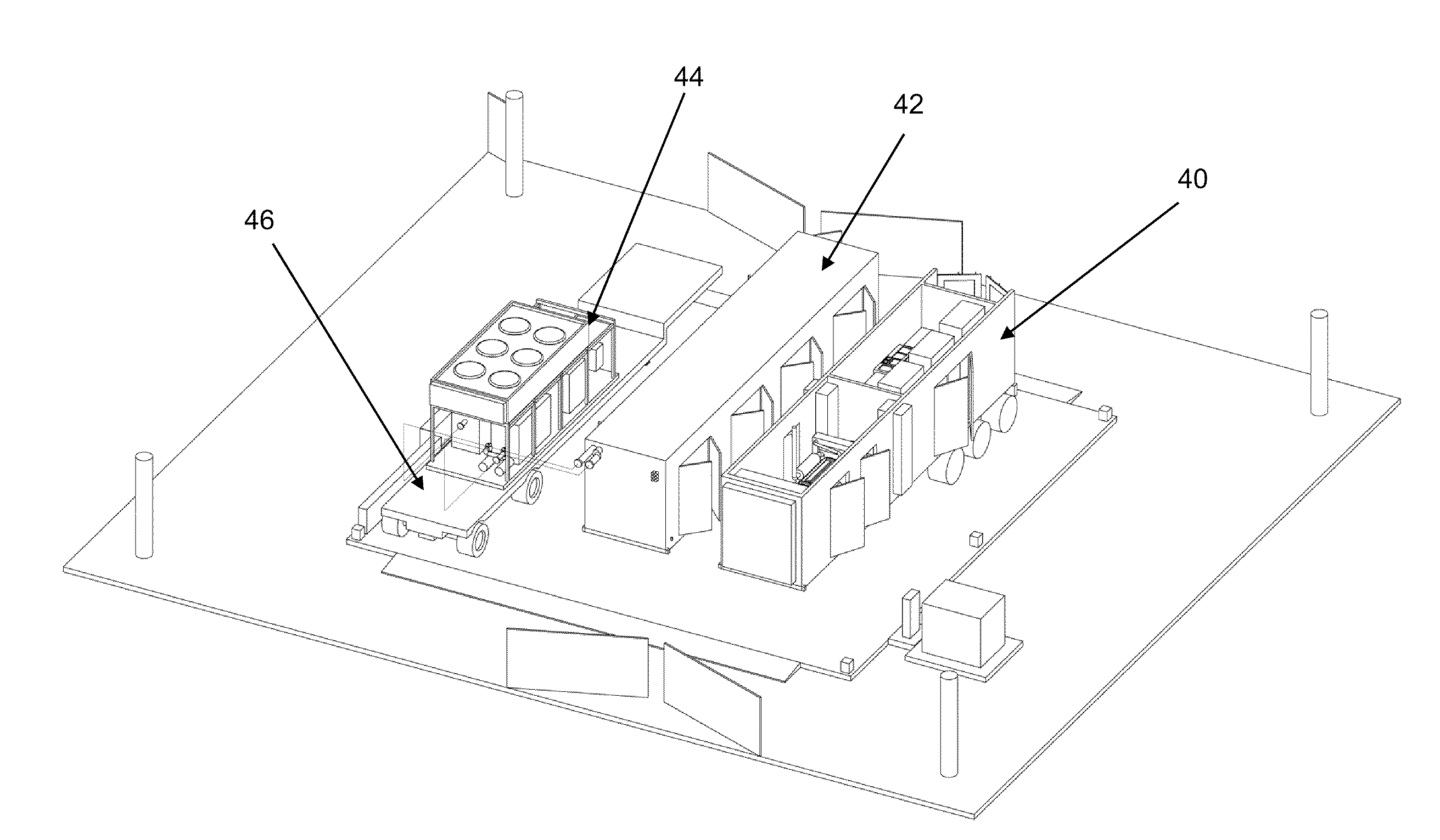
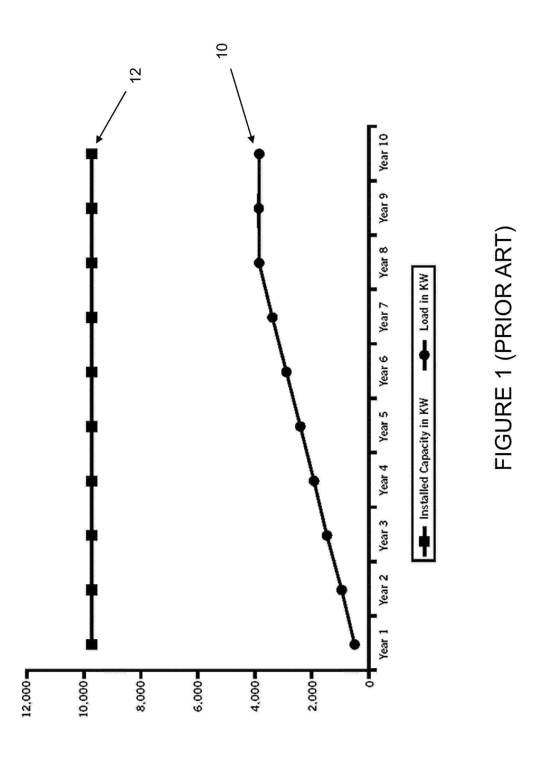
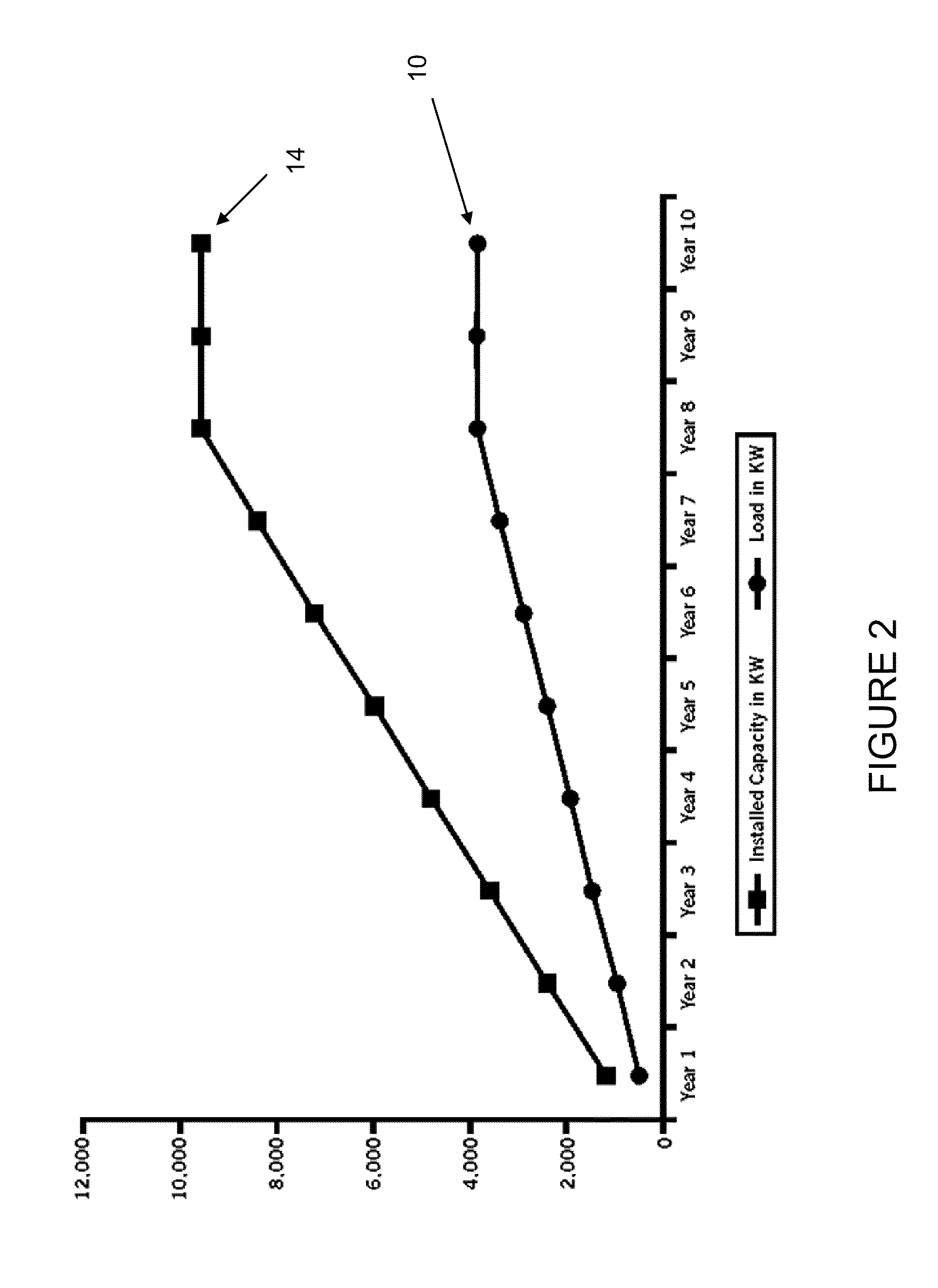
[0036]Known continuous power systems tend to be housed in permanent brick and mortar installations. Such installations may take many months or even years to build, and they tend to be not easily...


PUM


Abstract

It is an object of this disclosure to provide an efficient continuous power system that may be deployed quickly and at low cost to a variety of destinations. The containerized nature of the presently disclosed system may allow these advantages to be attained. The disclosed system is particularly well suited for deployment in data center applications, but one of ordinary skill will recognize that it may be useful in a variety of situations.

Description

CROSS-REFERENCE TO RELATED APPLICATIONS[0001]This application claims priority to U.S. Provisional Patent Application Ser. No. 61 / 310,775, which is hereby incorporated by reference in its entirety.FIELD[0002]The present disclosure relates to power generation systems. More specifically, the present disclosure relates to portable, containerized power generation systems that may be housed in a standard shipping container. The present disclosure may be useful as a backup continuous power system in conjunction with the power grid, or as a primary power generation system at locations not serviced by a power grid.DESCRIPTION OF THE RELATED ART[0003]Traditionally, large-scale continuous power systems have required a heavy investment of time and capital to complete as a “brick and mortar” installation. Further, such brick and mortar systems may tend to have a set output capacity that cannot easily be upgraded as needs change. Therefore, in order to be viable for a period of many years, the sy...

Claims


Application Information

Patent Timeline
IPC IPC(8): H02J9/08
CPCG01R31/3627H02J9/061H02J13/0072Y04S20/248Y04S20/12Y02B70/3291Y02B90/222Y02P90/50G01R31/385H02J13/00018H02J2310/16H02J13/00004H02J13/00034Y02B90/20Y02B70/30
Inventor SCHOMBURG, MARKUSSCHRADER-HAUSMANN, UWEMURPHY, JAMESLANDIS, RONSCHUETZE, KARLWALTER, BRADLEY
Owner ACTIVE POWER INC
Why Eureka
Try Eureka