LED based pedestal-type lighting structure

a technology of pedestals and lighting structures, which is applied in the direction of discharge tubes luminescnet screens, semiconductor devices for light sources, lighting and heating apparatus, etc., can solve the problems of phosphor material degradation, heat retention, and optical loss when light is reflected, and achieve the effect of reliable and efficien

Active Publication Date: 2011-09-08
IDEAL IND LIGHTING LLC
View PDF40 Cites 126 Cited by
  • Summary
  • Abstract
  • Description
  • Claims
  • Application Information

AI Technical Summary

Benefits of technology

[0013]The present invention provides various embodiments of lamps and bulbs that are efficient, reliable and cost effective and can be arranged to provide an omnidirectional emission pattern. Different embodiments can comprise solid state emitters arranged on a pedestal having thermal management features to control heat build-up in the emitters. These embodiments can also comprise shaped remote phosphors that can also have thermal management features to control conversion heat build-up in the remote phosphor. Different embodiments can also have diffuser features to generate the desired emission pattern for the lamps and bulbs.

Problems solved by technology

While the reflective cup 13 may direct light in an upward direction, optical losses may occur when the light is reflected (i.e. some light may be absorbed by the reflector cup due to the less than 100% reflectivity of practical reflector surfaces).
In addition, heat retention may be an issue for a package such as the package 10 shown in FIG. 1a, since it may be difficult to extract heat through the leads 15A, 15B.
This elevated operating temperature can cause degradation of the phosphor material over time.
It can also cause a reduction in phosphor conversion efficiency and a shift in conversion color.
These designs, however, do not provide optimized omnidirectional emission that fall within standard uniformity requirements.
These bulbs also contain a large number of interconnected LEDs making them prohibitively complex, expensive and unreliable.
This makes these LED bulbs generally impractical for most illumination purposes.
This arrangement, however, does not provide omnidirectional emission patterns, but instead provides a pattern that is substantially forward biased.
The mesa for this bulb also comprises a hollow shell, which can limit its ability to thermally dissipate heat from the emitters.
This can limit the drive current that can be applied to the LEDs.
This design is also relatively complex, using several LEDs, and not compatible with large volume manufacturing of low-cost LED bulbs.

Method used


Image

  • LED based pedestal-type lighting structure
  • LED based pedestal-type lighting structure
  • LED based pedestal-type lighting structure

Examples


Embodiment Construction

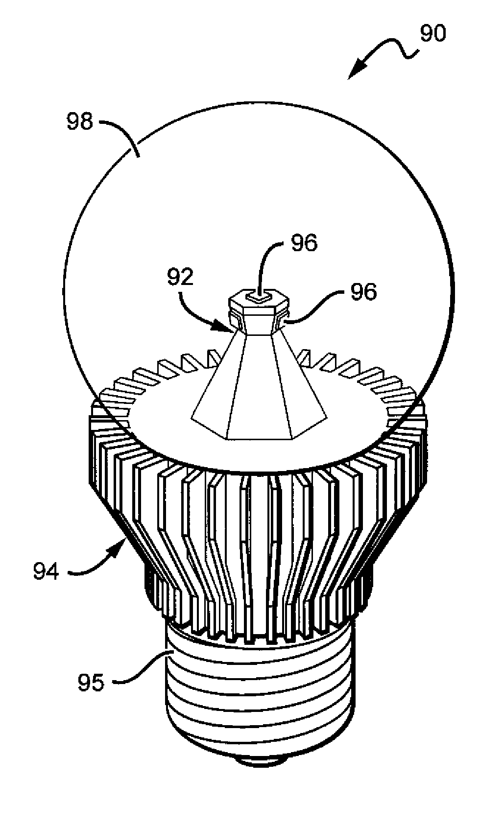
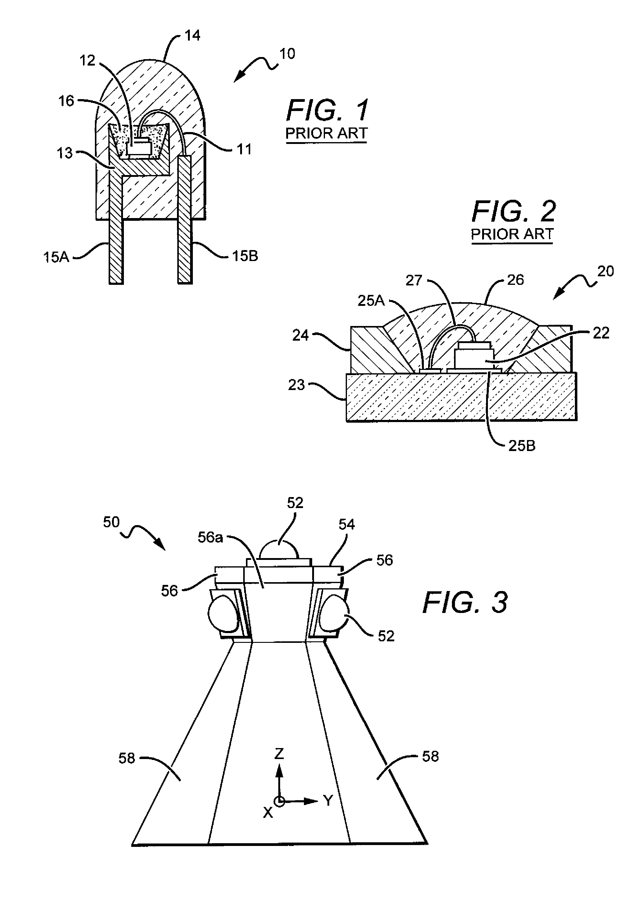
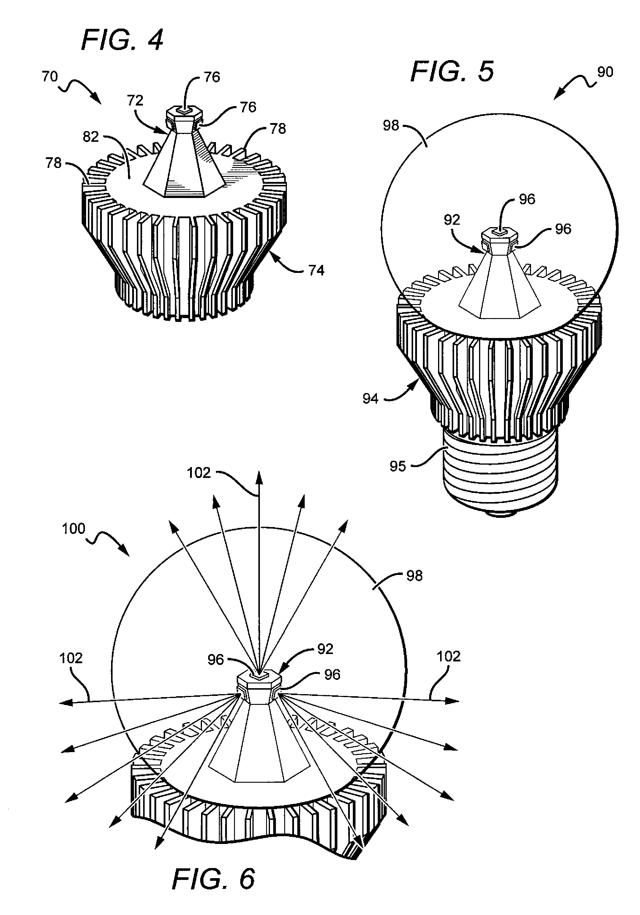
[0035]The present invention is directed to different embodiments of a lamp structure providing LED chips mounted to a thermally conductive pedestal. This allows for the LED lamp to near uniform omnidirectional light emission pattern modeling that of a traditional incandescent light bulb. Some LED bulbs according to the present invention are particularly applicable to uses as A-bulb replacement LED lamps. The embodiments according to the present invention consists of a particular shaped pedestal having surfaces compatible for mounting solid state emitters, and the pedestals can be made of thermally conductive materials or have elements that provide thermal conduction away from the emitters. Some embodiments of the pedestal can contain multiple LED based emitters, at least some of which emit in different directions away from the pedestal. When used with remote phosphor and diffuser domes, the particular angles and emission patterns of the LEDs can give the lamps an omnidirectional emi...


PUM


Abstract

LED based lamps and bulbs are disclosed that comprise a pedestal having a plurality of LEDs, wherein the pedestal at least partially comprises a thermally conductive material. A heat sink structure is included with the pedestal thermally coupled to the heat sink structure. A remote phosphor is arranged in relation to the LEDs so that at least some light from the LEDs passes through the remote phosphor and is converted to a different wavelength of light. Some lamp or bulb embodiments can emit a white light combination of light from the LEDs and the remote phosphor. These can include LEDs emitting blue light with the remote phosphor having a material that absorbs blue light and emits yellow or green light. A diffuser can be included to diffuse the emitting light into the desired pattern, such as omnidirectional.

Description

[0001]This application claims the benefit U.S. Provisional Patent Application Ser. No. 61 / 339,516 to Tong et al., entitled “LED Lamp Incorporating Remote Phosphor With Heat Dissipating Features”, and filed on Mar. 3, 2010.BACKGROUND OF THE INVENTION[0002]1. Field of the Invention[0003]This invention relates to solid state lamps, and bulbs and in particular to light emitting diode (LED) based lamps and bulbs capable of providing omnidirectional emission patterns similar to those of filament based light sources.[0004]2. Description of the Related Art[0005]Light emitting diodes (LED or LEDs) are solid state devices that convert electric energy to light, and generally comprise one or more active layers of semiconductor material sandwiched between oppositely doped layers. When a bias is applied across the doped layers, holes and electrons are injected into the active layer where they recombine to generate light. Light is emitted from the active layer and from all surfaces of the LED.[000...

Claims


Application Information

Patent Timeline
Patent Type & Authority Applications(United States)
IPC IPC(8): H01J61/52H01J1/62
CPCF21K9/00F21K9/135F21V3/00F21Y2101/02F21V29/773F21Y2111/007F21K9/56F21V3/04F21Y2111/001H01L2924/181H01L2224/32245H01L2224/48091H01L2224/48247H01L2224/73265F21K9/232F21K9/64F21Y2115/10F21Y2107/00F21Y2107/40H01L2924/00012H01L2924/00014H01L2924/00
Inventor TONG, TAOLETOQUIN, RONANKELLER, BERNDLOWES, THEODORETARSA, ERIC
Owner IDEAL IND LIGHTING LLC
Why Eureka
Try Eureka