This helps you quickly interpret patents by identifying the three key elements:
Problems solved by technology
Method used
Benefits of technology
Benefits of technology
[0004]Some battery chemistries (such as, for example, Lithium (“Li”), Lithium-ion (“Li-ion”) and other Li-based chemistries) require precise charging schemes and charging operations with controlled discharge. Insufficient charging schemes and uncontrolled discharging schemes may produce excessive heat build-up, excessive overcharged conditions and/or excessive overdischarged conditions. These conditions and build-ups can cause irreversible damage to t
Problems solved by technology
Insufficient charging schemes and uncontrolled discharging schemes may produce excessive heat build-up, excessive overcharged conditions and/or excessive overdischarged conditions.
These conditions and build-ups can cause irreversible damage to the batteries and can severely impact the battery's capacity.
Various factors, such as, for example, exces
Method used
Image
Click on the blue label to locate the original text in one second.
Reading with bidirectional positioning of images and text.
Examples
Embodiment Construction
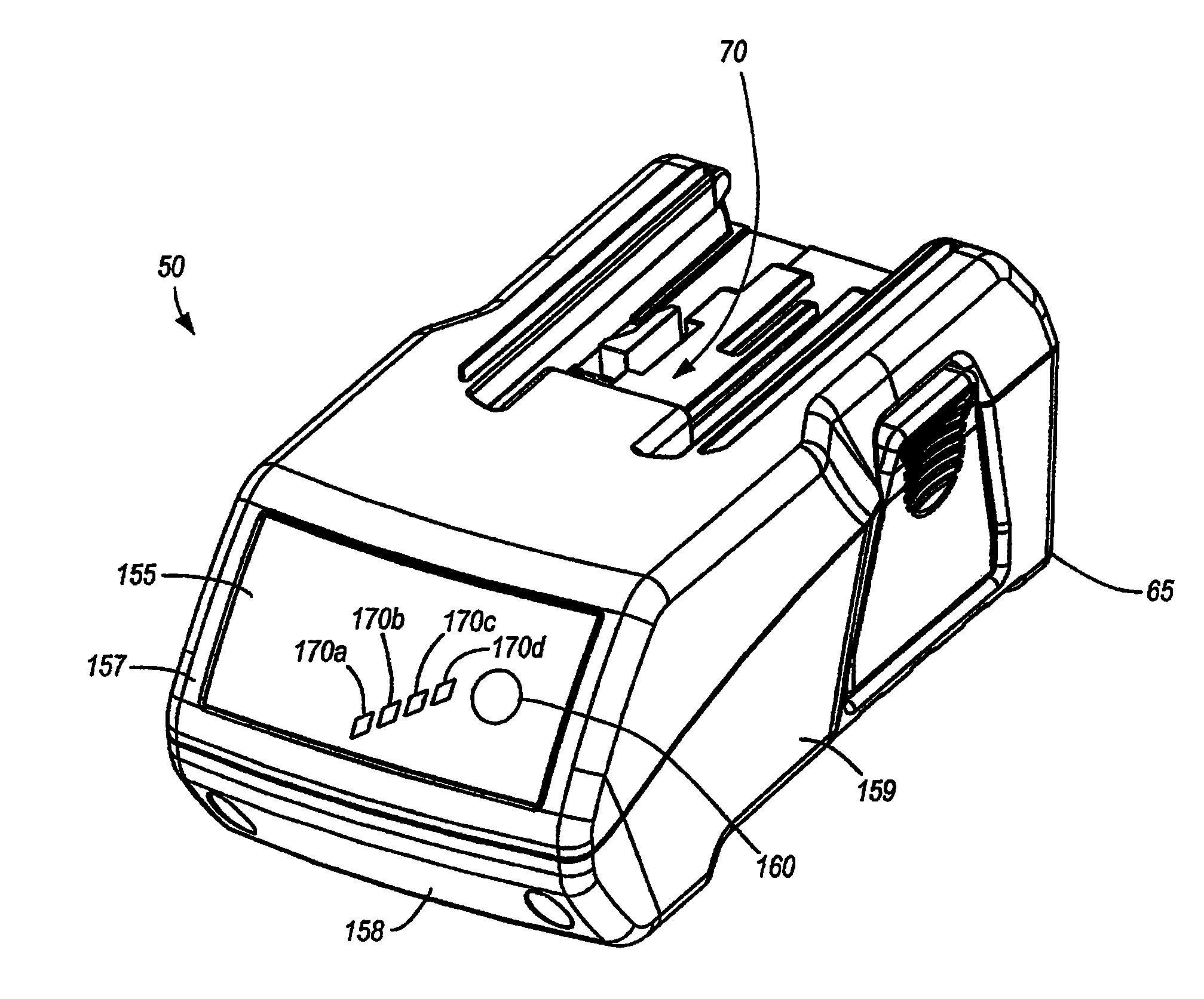
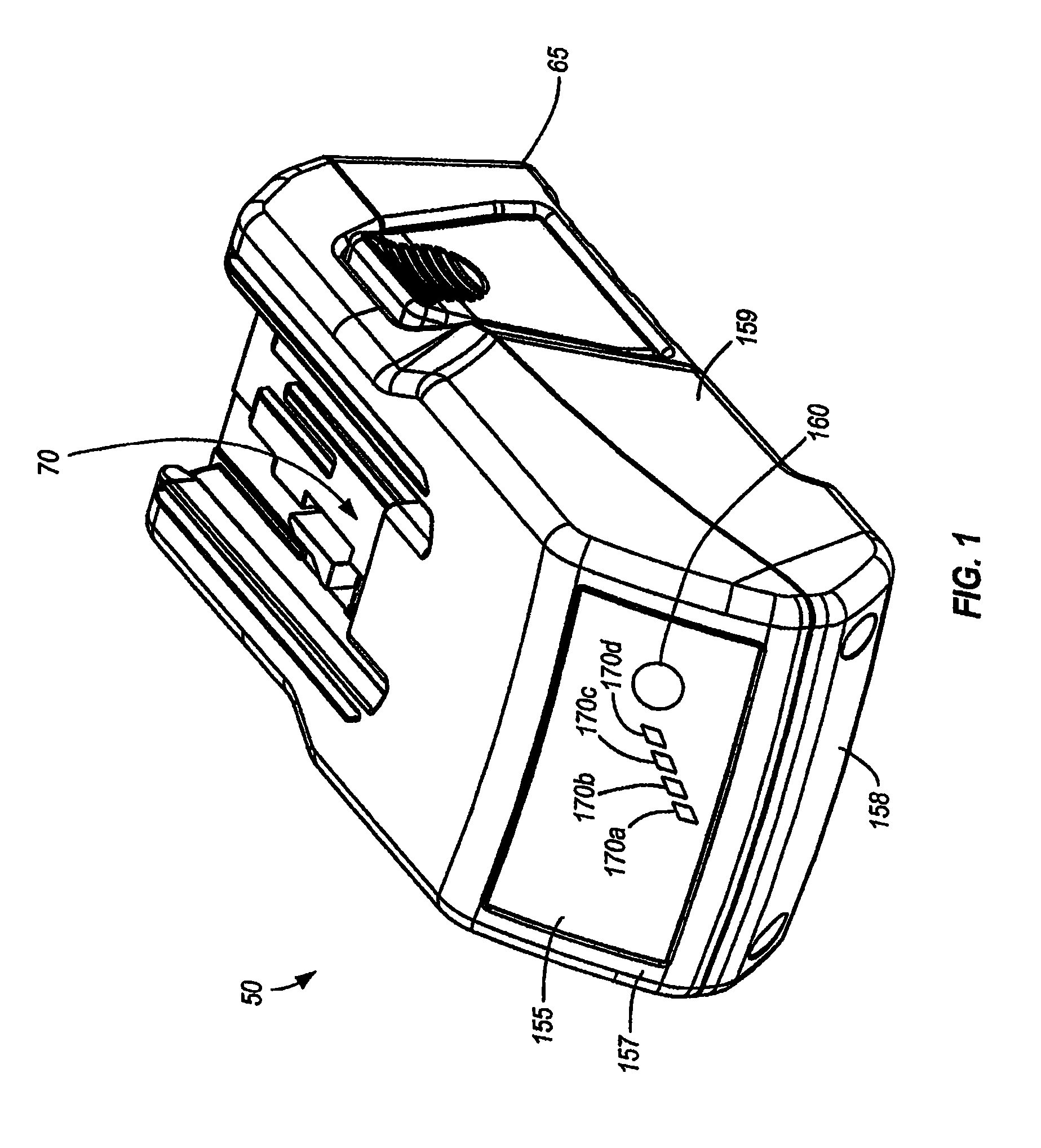
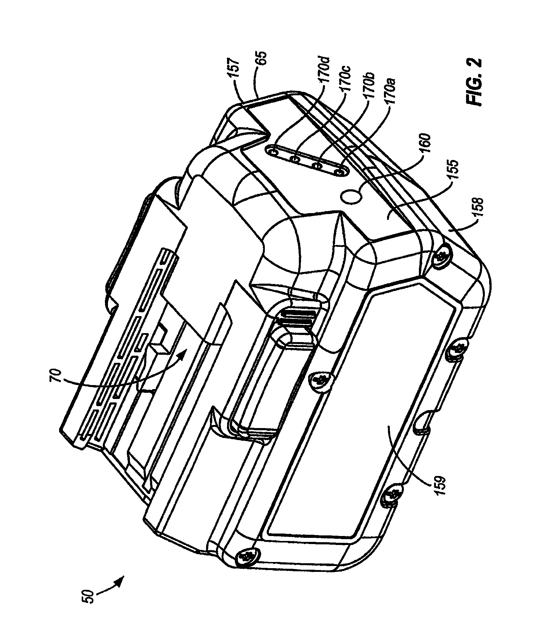
[0084]A battery pack or battery 50 is illustrated in FIGS. 1-3. The battery 50 can be configured for transferring power to and receiving power from one or more electrical devices, such as, for example, a power tool 55 (shown in FIGS. 4-5), a battery charger 60 (shown in FIG. 24) and the like. As shown in the constructions illustrated in FIGS. 4 and 5, the battery 50 can transfer power to various power tools, such as a circular saw 56 and a driver drill 58, for example. In some constructions and in some aspects, the battery 50 can supply a high discharge current to electrical devices, such as, for example, a power tool 55, having high-current discharge rates. For example, the battery 50 can power a wide range of power tools 55 including a circular saw 56, a driver drill 58, and the like, as shown in FIGS. 4 and 5.
[0085]In some constructions and in some aspects, the battery 50 can have any battery chemistry such as, for example, lead-acid, Nickel-cadmium (“NiCd”), Nickel-Metal Hydride...
PUM
Abstract
A system and method for battery protection. In some aspects, a battery pack includes a housing, a cell supported by the housing, a circuit supported by a flexible circuit board. The circuit is operable to control a function of the battery pack.
Description
RELATED APPLICATIONS[0001]The present patent application is a continuation of prior-filed, U.S. patent application Ser. No. 12 / 876,190, filed on Sep. 6, 2010, now U.S. Pat. No. 7,944,181, which is a continuation of U.S. patent application Ser. No. 12 / 709,939, filed on Feb. 22, 2010, now U.S. Pat. No. 7,791,318, which is a continuation of U.S. patent application Ser. No. 12 / 372,013, filed on Feb. 17, 2009, now U.S. Pat. No. 7,667,437, which is a continuation of U.S. patent application Ser. No. 11 / 617,365, filed on Dec. 28, 2006, now U.S. Pat. No. 7,504,804, which is a continuation of U.S. patent application Ser. No. 11 / 322,862, filed on Dec. 30, 2005, now U.S. Pat. No. 7,164,257, which is a divisional of U.S. patent application Ser. No. 10 / 720,027, filed on Nov. 20, 2003, now U.S. Pat. No. 7,157,882, which claims the benefit of U.S. Provisional Patent Application No. 60 / 428,358, filed on Nov. 22, 2002; No. 60 / 428,450, filed on Nov. 22, 2002; No. 60 / 428,452, filed on Nov. 22, 2002; No...
Claims
Application Information
Patent Timeline
Application Date:The date an application was filed.
Publication Date:The date a patent or application was officially published.
First Publication Date:The earliest publication date of a patent with the same application number.
Issue Date:Publication date of the patent grant document.
PCT Entry Date:The Entry date of PCT National Phase.
Estimated Expiry Date:The statutory expiry date of a patent right according to the Patent Law, and it is the longest term of protection that the patent right can achieve without the termination of the patent right due to other reasons(Term extension factor has been taken into account ).
Invalid Date:Actual expiry date is based on effective date or publication date of legal transaction data of invalid patent.
