Ball with positioning system

a positioning system and ball technology, applied in the field of balls, can solve problems such as electrical circuit breakage in balls, and achieve the effects of improving the reception of signals, preventing subsequent tearing of substrates, and increasing cross polarization

Inactive Publication Date: 2011-09-08
PRAZZA
View PDF6 Cites 17 Cited by
  • Summary
  • Abstract
  • Description
  • Claims
  • Application Information

AI Technical Summary

Benefits of technology

[0014]By forming the antenna on the laminate circuit material the flexible substrate can be punched or cut into a desired surface area, in particular in the form of the antenna. The antenna preferably comprises to individual arms. In an embodiment the arms are positioned adjacent each other. A cut divides the two arms. At the connecting end of the arms (proximal to the circuit) a further (unplated) hole can be formed, e.g. by punching to prevent subsequent tearing of the substrate.
[0015]In an embodiment the antenna is folded out of a primary surface of the electrical circuit. By forming the antenna on the flexible substrate, the antenna is formed in a two dimensional surface. The flexible substrate allows bending of the antenna out of the original or primary surface of the flexible substrate. By folding a three dimensional antenna is obtained allowing transmittal of signal in all directions, improving the reception of that signal by a tracking system operated by a user.
[0016]In an embodiment the flexible substrate having the antenna comprises a connector, formed e.g. by punching, for allowing to connect the folded antenna to another part of the substrate. In an embodiment the substrate comprises the electrical circuit formed on a first surface of the substrate. At one end of the first surface the antenna is formed, extending from the first surface. At least a part of the antenna can be folded an connected to an opposite end of the first surface. This allows folding the antenna part to a semi-circle. This will increase cross polarization. Although the cross polarization will influence the quality (gain) of the antenna, a ball such as a golf ball will land in any orientation to the ground, allowing radiating partly with horizontal and partly with vertical polarization. This decreases the antenna gain but a vertically polarized EM wave does propagate better close to the ground.

Problems solved by technology

Repeated shock tests resulted in broken electrical circuits in the ball.

Method used


Image

  • Ball with positioning system
  • Ball with positioning system
  • Ball with positioning system

Examples


Embodiment Construction

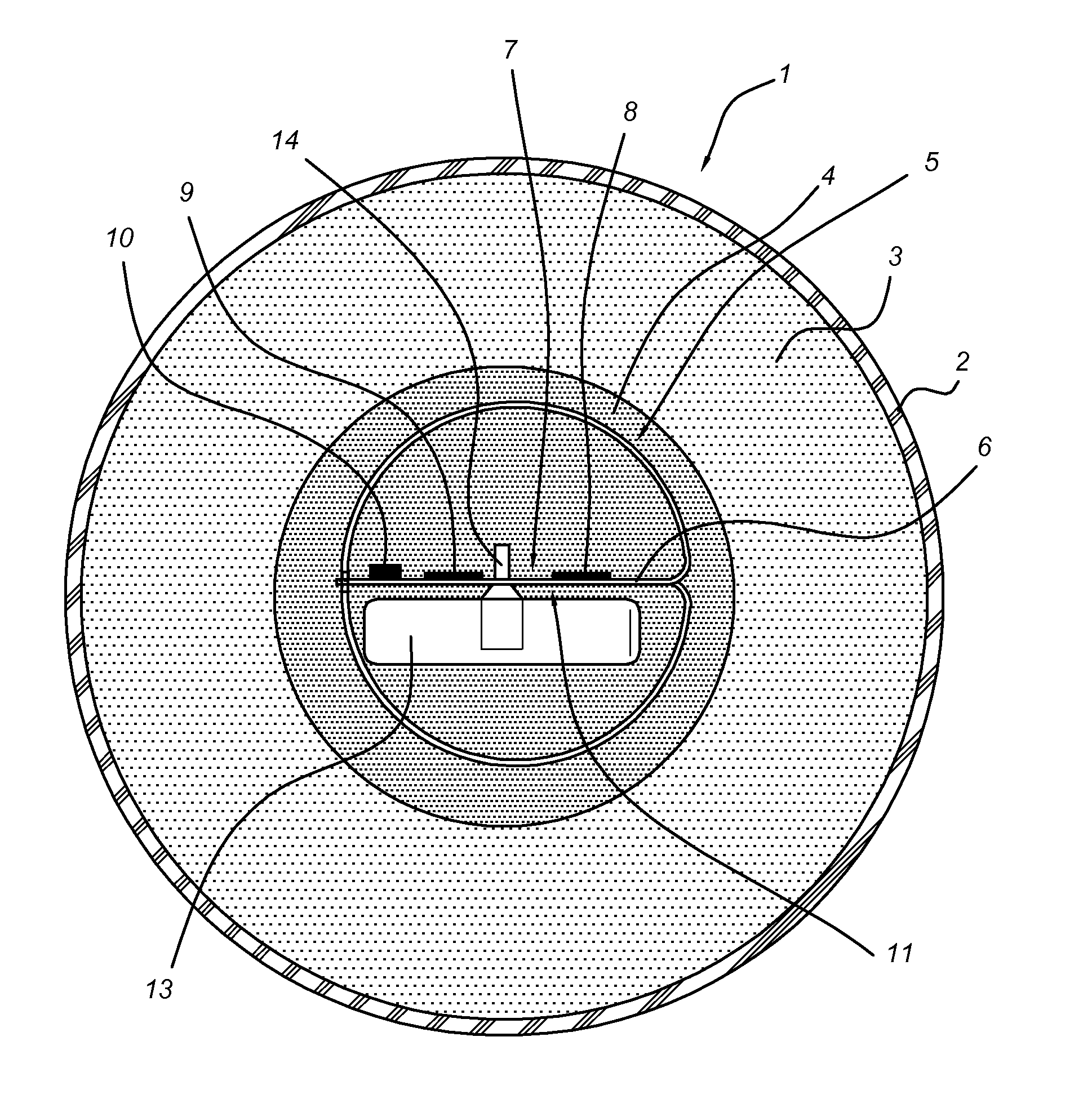
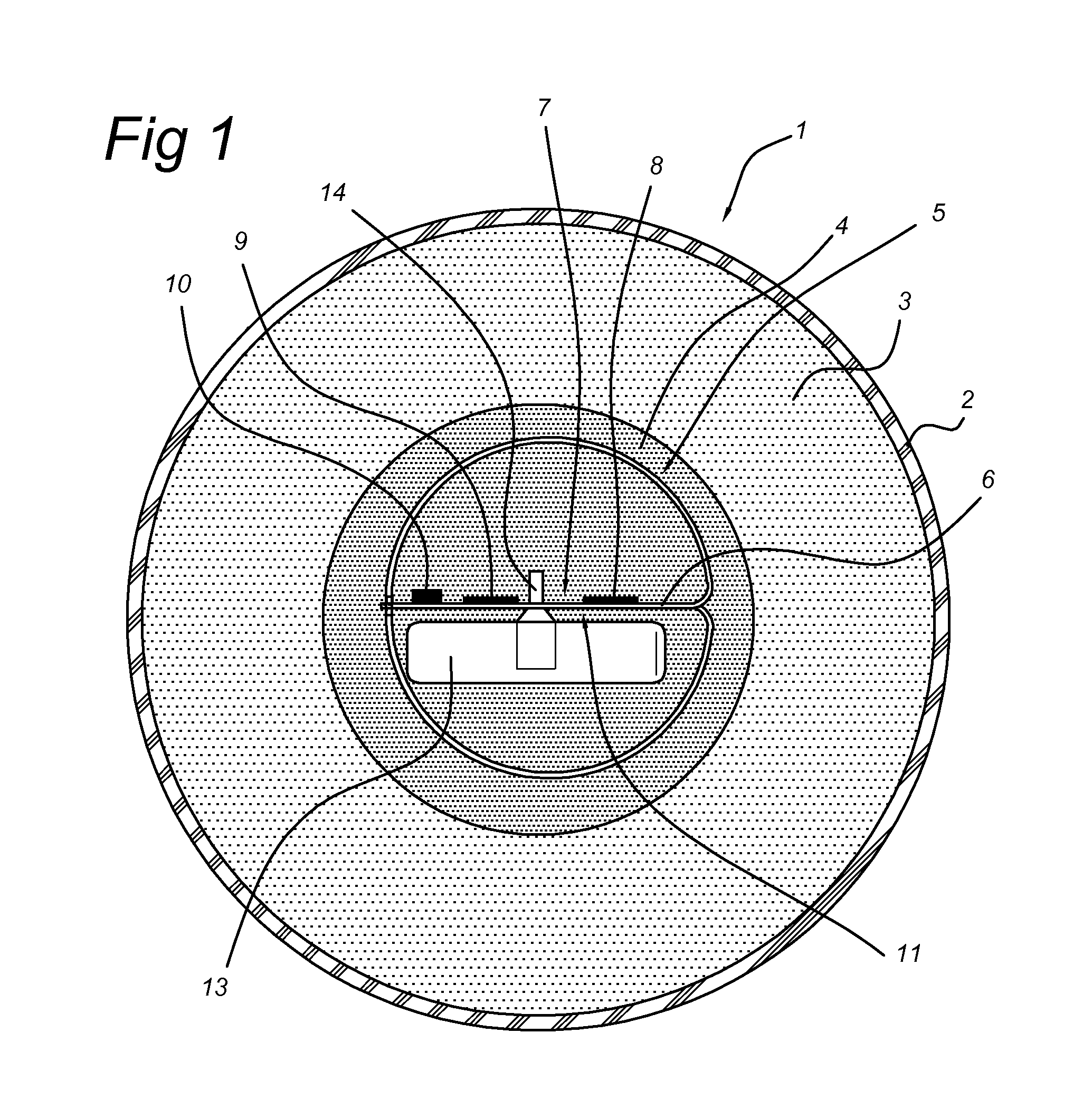
[0038]FIG. 1 shows a cross sectional view of a golf ball 1. A coating of ionomer 2 surrounds a body of PBD in which a moulded body of polyurethane (PUR) 4 is received. The PUR 4 is formed into a sphere. In the spherical mould a device 5 according to the invention was centered. Foam is injected into the mould (not shown separately) and hardens. Injecting the foam into the mould results in filling up all or generally all spaces surrounding the device 5. The PUR 4 forms a protective cover surrounding the device 5. It will absorb shocks.

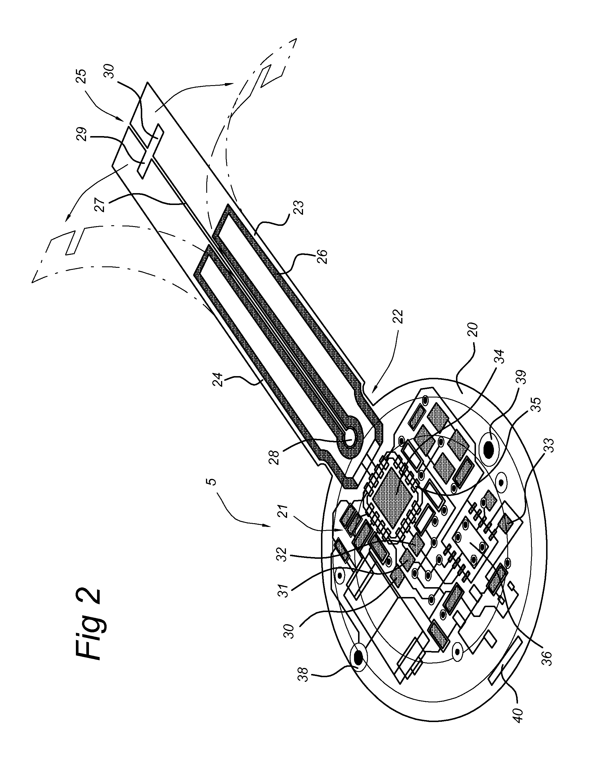
[0039]The device 5 comprises a first surface 6. Onto a first side 7 of the device 5 surface mounted device (SMD) 8-10 are mounted. In an embodiment SMD 8 is a Texas Instruments CC2550 arranged to perform transmitter functions. A further SMD 9 could be a microcontroller. Another SMD 10 could be a FET.

[0040]The substrate 6 is a flexible substrate such as a liquid crystalline polymer available from Rogers corporation sold under the trademark name ULTRALAM® ...


PUM


Abstract

A ball (1) for use in a sporting activity can comprise a body having an electrical circuit (21) on a flexible substrate (20) received therein. The electrical circuit (21) comprises a dipole antenna (26) integrally formed with the electrical circuit (21) on the flexible substrate (20). The dipole antenna can comprise two arms (23, 24) each folded in a semi-circular shape.

Description

CLAIM OF PRIORITY[0001]This application claims the benefit of priority from the following application, incorporated by reference herein: European Patent Application No. 10155633.0 entitled “BALL WITH POSITIONING SYSTEM AND POSITIONING SYSTEM FOR A BALL;” by inventor John Van Driel; filed on Mar. 5, 2010.FIELD OF THE INVENTION[0002]The invention relates to a ball for use in a sporting activity.BACKGROUND[0003]From US 2009 / 0137340 a golf ball is known having a tracking system. A microchip is embedded in the ball. The microchip can send information specific for the location to a receiver of a tracking system. This allows the user to track the golf ball.[0004]The electrical system received in the ball, especially a golf ball, will experience intense shocks. The electrical system should be shockproof.SUMMARY OF THE INVENTION[0005]It is a goal of the invention to provide an improved ball for use in a sporting activity.[0006]According to an aspect of the invention an improved ball comprise...

Claims


Application Information

Patent Timeline
Patent Type & Authority Applications(United States)
IPC IPC(8): H01Q1/22
CPCA63B37/0003A63B37/0055A63B2024/0053A63B2225/50G06K19/07749G01V15/00G06K19/045G06K19/07728A63B2225/54
Inventor VAN DRIEL, JOHN
Owner PRAZZA
Why Eureka
Try Eureka