Supercharge Your Innovation With Domain-Expert AI Agents!

Stepped Surface Propeller

Active Publication Date: 2011-09-08
TWIN DISC
View PDF10 Cites 4 Cited by
  • Summary
  • Abstract
  • Description
  • Claims
  • Application Information

AI Technical Summary

Benefits of technology

[0010]This invention relates to marine surface propellers and more particularly to a surface piercing propeller. The present invention provides an improved propeller blade for a multi-bladed surface piercing marine propeller by adding a geometric feature called a “step,” which is a raised surface of a specific type and placement, on either the blade front face, the blade back, or both surfaces. The surface piercing propeller blade of the current invention, controls the pressure and water flow over the blade face and / or blade back thereby increasing the thrusting force among other advantages. The surface piercing propeller blade of the current invention, however, controls the pressure and water flow over the blade face and / or blade back thereby increasing the total thrusting force among other advantages. This force also produces drag such that another advantage of this invention is achieving maximum lift with minimum drag.
[0011]A major component of thrust is produced by the complex turning of water flow over the blade pressure face. Surface propellers existing today have a pressure face geometry that is flat or cambered with an annex at the trailing edge thereby creating pressure peaks nearby the leading and trailing blade edges. The central portion of the blade generally has a low pressure zone. The addition of a geometric step feature on the blade face between the leading and trailing edges increases the pressure near this feature and increases the overall pressure (blade pressure face loading) thereby increasing thrusting force.
[0012]Therefore one aspect of this invention comprises a positive step on the blade face which can be a ramp, cup, interceptor or other geometric annex, addition or intervention. The positive step is a structure that rises in a positive direction from the local surface, i.e. a surface which is near to the structure, when traversing the blade surface in a given manner, wherein positive is defined by the local surface normal directed away from the surface. The step feature is located at between one fifth and four fifths of the chord length, i.e. mid-chord, (wherein a chord is an imaginary straight line connecting leading and trailing edges of a curved or non-planar blade surface) so as to create a high pressure peak or zone in what is now a low pressure zone. This step will more equally distribute pressure over the blade face and result in a higher blade face loading. This will allow the use of smaller diameters and thus a higher pitch diameter ratio propeller and its subsequent higher efficiency.

Problems solved by technology

Application of the basic principles to actual operating conditions, however, involves the interplay of many complex variables caused by the three dimensional complex blade face surfaces of the propeller.
Consequently, the effective functioning of a propeller blade, although theoretically simple, is actually extremely complex, especially at high operational speeds, as is well known to those in this art.
Therefore surface propeller designers constantly experiment with propeller variations and periodically discover blade geometries that empirically function unexpectedly well, or unexpectedly poorly, for reasons that are not fully understood.
Effective performance of the surface piercing propeller during forward movement depends upon obtaining pressure on the front face of the propeller, which results in the propeller's thrust.
However, the central portion of the blade face chord is a low pressure zone between these two pressure peaks, which fails to maximize the pressure on the blade face.
Thus, current surface piercing propeller blades fail to maximize their thrust for a given rotational velocity (RPM) and size (effective radius or surface area).
In addition, there are no known features for the back side of a surface propeller directed toward minimizing pressure.
Because prior art surface propeller blades fail to provide a solution to the problem of providing a highly efficient and compact propeller blade then what is needed is a surface piercing propeller blade that maximizes the thrusting force by maximizing pressure for a given area on the blade pressure face and minimizing the pressure for a given area on the blade vacuum face.

Method used


Image

  • Stepped Surface Propeller
  • Stepped Surface Propeller
  • Stepped Surface Propeller

Examples


Embodiment Construction

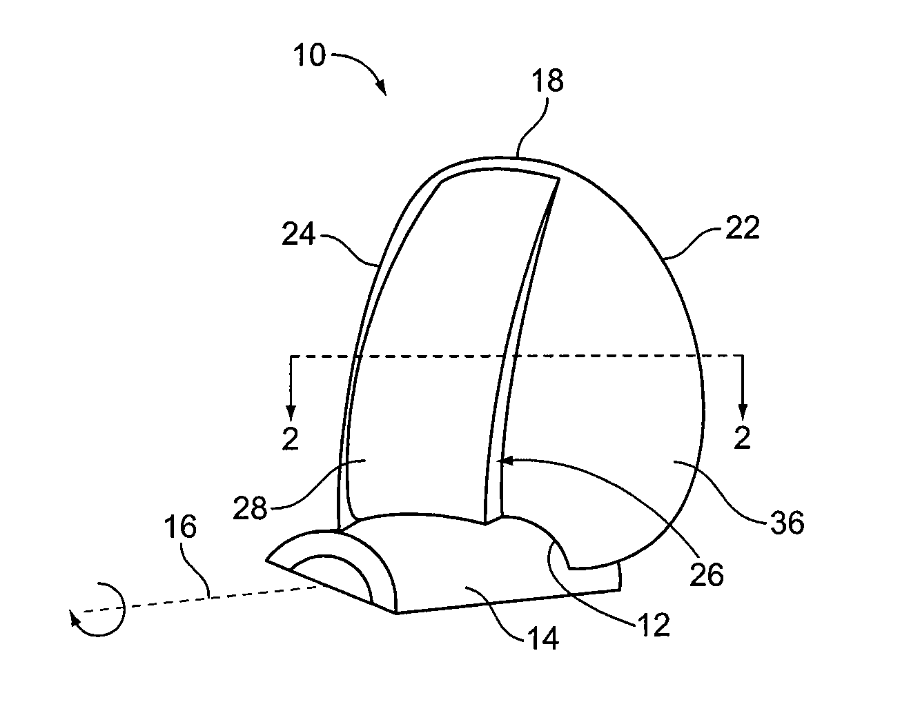
[0048]With reference now to the drawings, and particularly to FIG. 1, there is shown a first embodiment of the surface propeller blade 10 of the preferred embodiments. The blade 10 has a blade root 12 securably attached to a propeller hub 14 which rotates about a propeller axis 16. Given that the thrust on a surface propeller is generated by the blade face 36 accelerating the mass of water it is confronting (Newton's second law) then the water exerts an equal but opposite force forward on the blade face (Newton's third law). The force produced by the deflected volume of water is the thrust (or lift), which moves the marine vehicle in the forward direction as shown in FIG. 1. Although only one propeller blade 10 is depicted, a propeller formed of such blades will normally have a plurality of blades, for example, three or more.

[0049]With further reference to FIG. 1, the surface propeller blade 10, has a root 12 and a tip 18 distal from the blade root 12. The blade 10 comprises a leadi...


PUM


Abstract

A marine surface propeller, and blade therefore, which is surface piercing and partially submerged, and includes a blade geometry that improves distribution of pressure and control to wetted and ventilated regions. Preferably, the feature has a positive step (ramp, cup, interceptor, indent or other geometric addition or intervention) between one fifth and four fifths chord length so as to create a high pressure peak or zone in what is now a low pressure zone on either the blade face or back or both and to create speed controllable wetted and ventilated regions.

Description

BACKGROUND OF THE INVENTION[0001]1. Field of the Invention[0002]The surface propeller or surface piercing propeller is a partially submerged naturally ventilated propeller that during normal forward movement of the marine vessel achieves all of its thrust from blade face pressure because the blade back is nearly or completely ventilated. Based on this functionality the blade front (or blade face) may be referred to as the pressure face and the blade back as the vacuum face.[0003]2. Description of the Related Art[0004]The function of a surface propeller is based upon basic principles which have been generally accepted for many decades. Application of the basic principles to actual operating conditions, however, involves the interplay of many complex variables caused by the three dimensional complex blade face surfaces of the propeller. Consequently, the effective functioning of a propeller blade, although theoretically simple, is actually extremely complex, especially at high operati...

Claims


Application Information

Patent Timeline
IPC IPC(8): B63H1/26
CPCB63H1/26F03B3/121B63H2001/185B63H1/14B63H1/28
Inventor ROLLA, PHILIP
Owner TWIN DISC
Features
  • R&D
  • Intellectual Property
  • Life Sciences
  • Materials
  • Tech Scout
  • Unparalleled Data Quality
  • Higher Quality Content
  • 60% Fewer Hallucinations
Learn More