Connector structure for high-frequency transmission lines

Inactive Publication Date: 2011-09-08
JJS COMM
View PDF20 Cites 0 Cited by
  • Summary
  • Abstract
  • Description
  • Claims
  • Application Information

AI Technical Summary

Benefits of technology

[0005]An object of the present invention is to provide a connector structure for high-frequency transmission lines, which has sim

Problems solved by technology

However, when present 75-Ohm system is required to be expanded to have bandwidth of 4.5 G, the electrical charac

Method used


Image

  • Connector structure for high-frequency transmission lines
  • Connector structure for high-frequency transmission lines
  • Connector structure for high-frequency transmission lines

Examples


Embodiment Construction

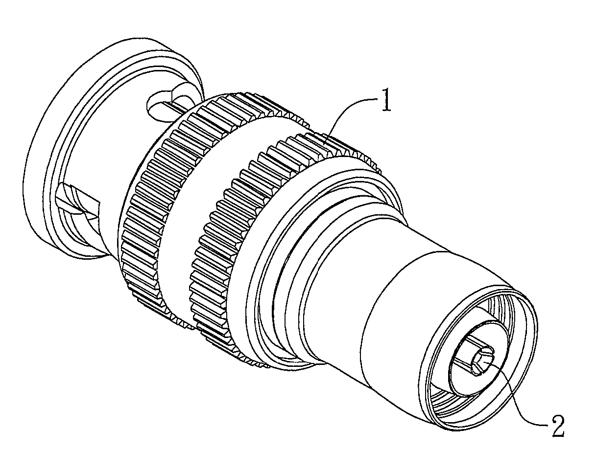
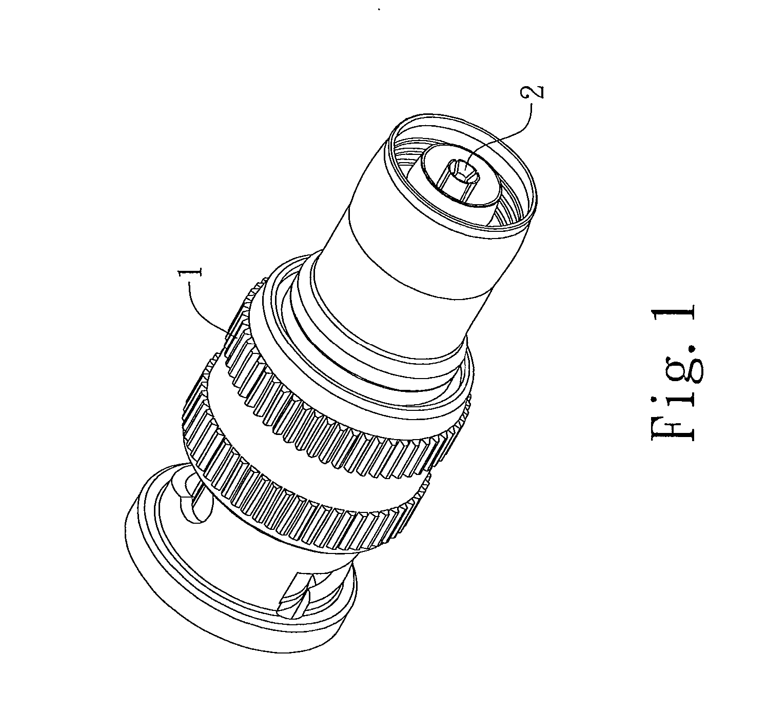
[0017]Please refer to FIGS. 1 to 3 showing an embodiment of a connector structure for high-frequency transmission lines according to the present invention.

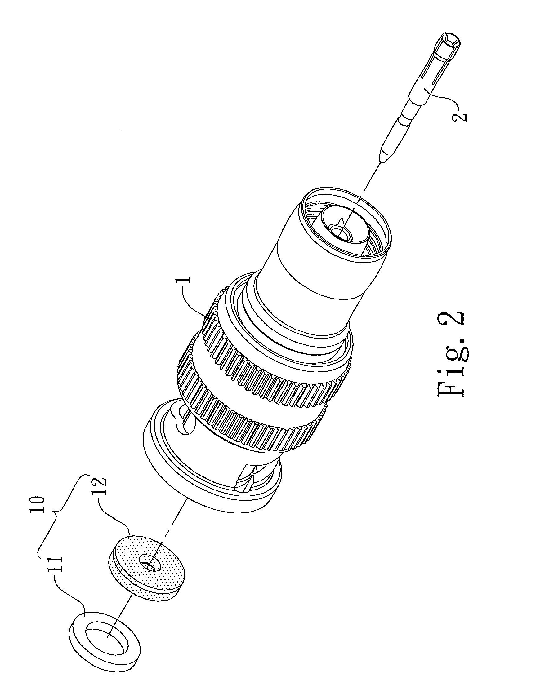
[0018]The present invention provides a connector structure for high-frequency transmission lines, which comprising a locking sleeve 1 used for receiving the connector 2 of a signal cable therein for signal transmission. The locking sleeve 1 comprises a hollow part 10 and the hollow part 10 is in the shape of a ring and is disposed in the locking sleeve 1. The hollow part 10 includes a hollow metal piece 11, so that when connected into the locking sleeve 1, the connector 2 of the signal cable is inserted through the hollow metal piece 11 of the hollow part 10.

[0019]In practice, the hollow part 10 can be formed integratedly into the locking sleeve 1. Alternatively, as referring to FIGS. 2 and 3, the hollow part 10 can be formed by combining the hollow metal piece 11 and a hollow plastic piece 12. The hollow metal piece 11 and the ho...


PUM


Abstract

A connector structure for high-frequency transmission lines comprises a locking sleeve used for receiving the connector of a signal cable therein for signal transmission, and is characterized in that: the locking sleeve comprises a hollow part and the hollow part is disposed in the locking sleeve, where the hollow part includes a hollow metal piece, so that when connected into the locking sleeve, the connector of the signal cable is inserted through the hollow metal piece of the hollow part.

Description

TECHNICAL FIELD[0001]The present invention relates to a connector structure for high-frequency transmission lines, whose structure is simple and whose electrical characteristics are improved to obtain high-transmission efficiency and low-reflection effects.BACKGROUND[0002]In modern life changing with each passing day, the average living standard is gradually improved. With this improvement, people are more particular about their material enjoyment and accordingly many high-technology products are invented. Some connectors are required to utilize these high-technology products in order to transmit signals and among the connectors the most well known is Bayonet Neil-Concelman (BNC) connector.[0003]Typically, the bandwidth of the BNC connector is between 0 to 3 GHz; the resistance thereof is between 50 to 75 Ohm; and the insertion loss thereof is about 0.2 dB. BNC connectors are widely applied in different field; for example, they can be used in following items: apparatuses for radio-f...

Claims


Application Information

Patent Timeline
IPC IPC(8): H01R13/625
CPCH01R13/625H01R24/40H01R9/0524H01R2103/00
Inventor WANG, SHOU-YING
Owner JJS COMM
Why Eureka
Try Eureka