Drill attachment

a technology for drilling machines and attachments, which is applied in the direction of tube shearing machines, manufacturing tools, metal working apparatuses, etc., can solve the problems of worm gear pairs and/or tooth segments being damaged on the cutting unit, high structural effort and comparatively heavy weight of the drilling machine headpiece, and facilitate the slippage of the transport ratchet, facilitate the simple interruption of the cutting process, and facilitate the effect of ratchet teeth

Inactive Publication Date: 2011-09-15
WEIDMULLER INTERFACE GMBH & CO KG
View PDF10 Cites 13 Cited by
  • Summary
  • Abstract
  • Description
  • Claims
  • Application Information

AI Technical Summary

Benefits of technology

[0012]By using a crank drive for the conversion of the rotary movement of the drive shaft into a translation movement of the transport ratchet member, one can bring about the advancement of at least one of the cutting blades by means of a simple and trouble-free mechanical arrangement.
[0022]A supporting sleeve, arranged on the head piece in a position axially with respect to the drive shaft, ensures a secure torque support of the cutting attachment with respect to the drilling machine that drives the cutting attachment.

Problems solved by technology

There is one disadvantage that is connected with the typical drilling machine head piece—namely, the high structural effort and the comparatively heavy weight of the drilling machine head piece as a result of the worm gear pair.
Under certain circumstances, the worm gear pair and / or the tooth segment could be damaged on the cutting unit.

Method used


Image

  • Drill attachment
  • Drill attachment
  • Drill attachment

Examples


Embodiment Construction

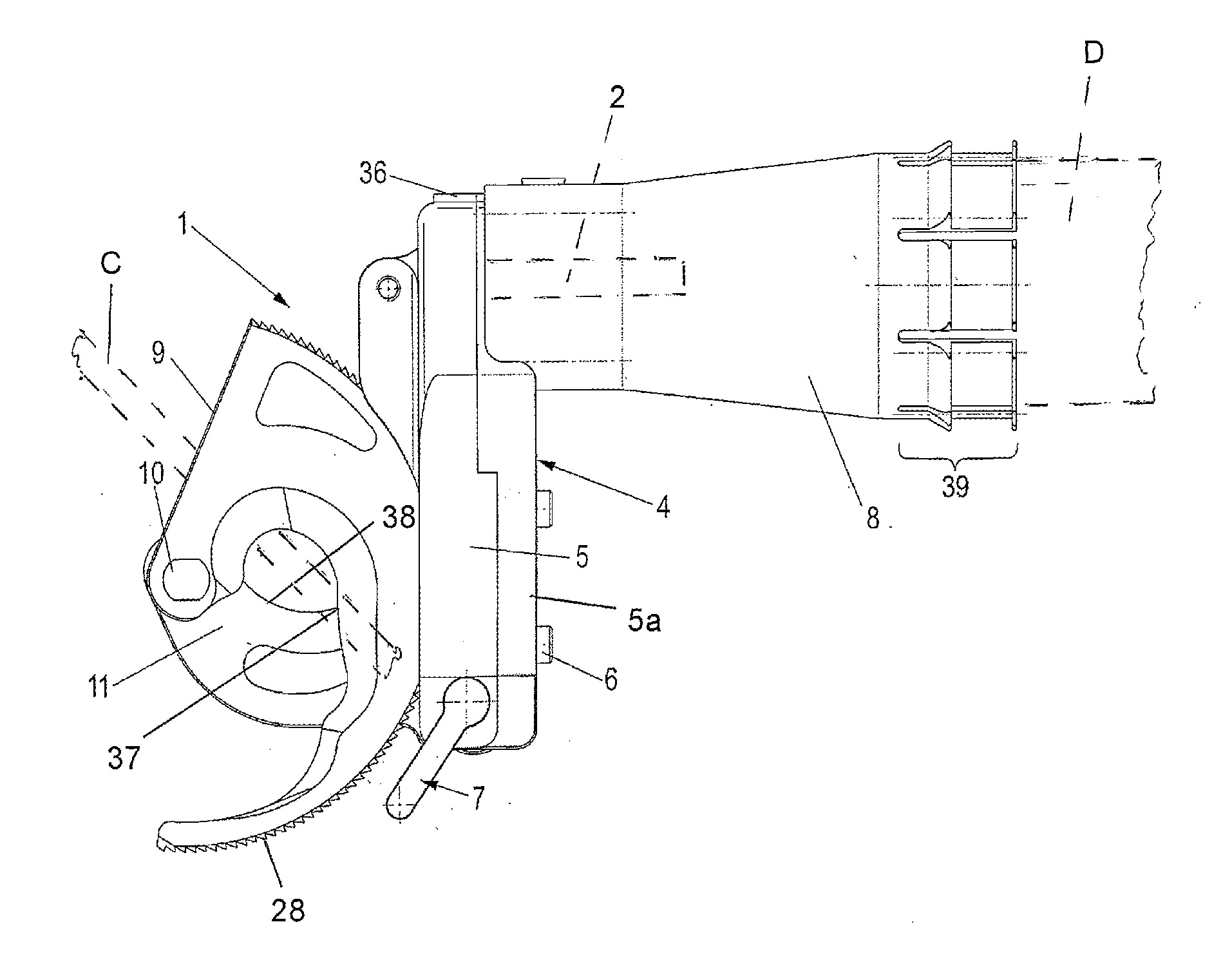
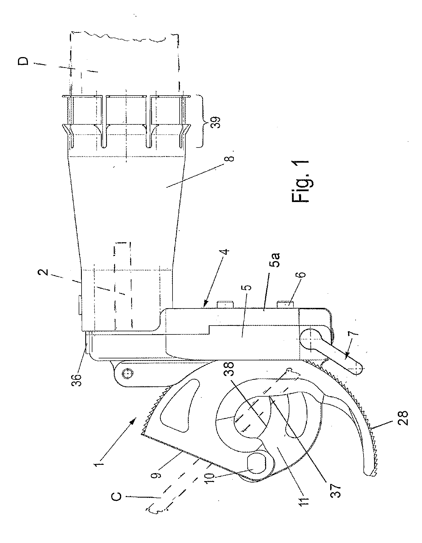
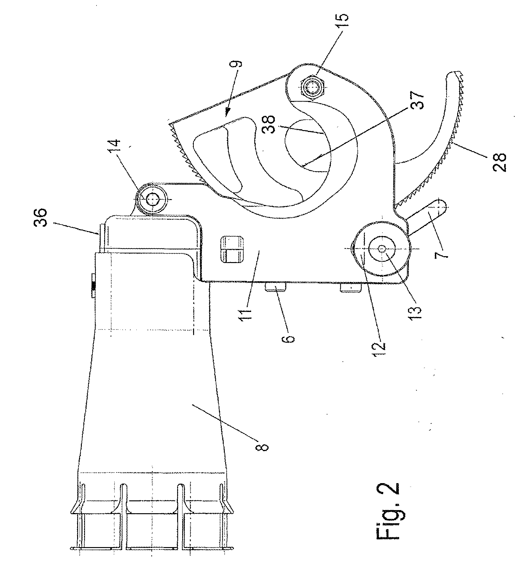
[0029]Referring first more particularly to FIGS. 1 and 2, the drill cutting attachment 1 of the present invention includes a sectional housing 4 including a body section 5 to which a removable cover section 5a is fastened by a plurality of bolts 6. Connected at one end with one end of the housing 4 by means of a cover cap 36 is a supporting sleeve 8. At its other end, the supporting sleeve 8 has an annular expansible resilient finger portion 39 adapted for removable connection with the operating end body portion of a hand-held electric drill D.

[0030]Pivotally connected with the housing 4 by pivot means 14 defining a disconnect pivot axis is a stationary cutting blade 11 having an sickle-shaped internal cutting edge 37. Pivotally connected by bolt 10 and lock nut 15 (FIG. 2) with the stationary cutting blade 11 for pivotal movement about a cutting pivot axis is the movable cutting blade 9 which also has a corresponding reversely-arranged sickle-shaped internal cutting edge 37. The ou...


PUM

PropertyMeasurementUnit
electricalaaaaaaaaaa
displacementaaaaaaaaaa
longitudinal displacementaaaaaaaaaa

Abstract

A drill cutting attachment for severing an electrical conductor includes a housing, a stationary cutting blade connected with the housing, a movable cutting blade pivotally connected with the stationary cutting blade for displacement about a given cutting pivot axis between open and closed positions relative to the stationary cutting blade, and a pawl and ratchet arrangement for displacing the movable cutting blade from the open position toward the closed position, thereby to sever an electrical conductor positioned between the blades. The pawl and ratchet arrangement includes a transport pawl member that is longitudinally reciprocated by a rotary drive shaft via either an eccentric and crank arm drive arrangement, or a cam and follower drive arrangement. The drive shaft has a free end with a hexagonal cross-sectional configuration for connection with the chuck of an electric drill, and an attachment sleeve connects the housing with the electric drill body.

Description

REFERENCE TO RELATED APPLICATIONS[0001]This application is a continuation of the International Application No. WO 2010 / 031658 which is based on the PCT Application PCT / EP2009 / 060911 filed Aug. 25, 2009, claiming priority of the German application No. DE 20 2008 012 415.8, filed Sep. 18, 2008.BACKGROUND OF THE INVENTION[0002]1. Field of the Invention[0003]A drill cutting attachment for severing an electrical conductor includes a housing, a stationary cutting blade connected with the housing, a movable cutting blade pivotally connected with the stationary cutting blade for displacement about a given cutting pivot axis between open and closed positions relative to said stationary cutting blade, and a pawl and ratchet arrangement driven by a drive shaft for displacing the movable cutting blade from the open position toward the closed position, thereby to sever an electrical conductor positioned between the blades.[0004]2. Description of Related Art[0005]A typical drilling machine head p...

Claims


Application Information

Patent Timeline
Patent Type & Authority Applications(United States)
IPC IPC(8): B23D29/00B23D17/04
CPCB23D29/002
Inventor BROEKER, THILODIERKS, CHRISTOPH
Owner WEIDMULLER INTERFACE GMBH & CO KG
Why Eureka
Try Eureka