Electric power steering assembly

a technology of electric power steering and assembly, which is applied in the direction of vehicle sub-unit features, vehicle design optimization, etc., can solve the problem of unsatisfactory noise produced by one or more of the associated components of the rack drive assembly

Inactive Publication Date: 2011-09-15
TRW AUTOMOTIVE US LLC
View PDF19 Cites 29 Cited by
  • Summary
  • Abstract
  • Description
  • Claims
  • Application Information

AI Technical Summary

Benefits of technology

[0043]Potential advantages of the electric power steering assemblies 10, 80 and 100 of the present invention is that the respective dampers 70, 82 and 101 should be effective to reduce system noise, vibration and harshness (NVH), should transmit system shock loads into the housing and thus into the vehicle; and should provide a self-centering feature of the associated components of the steering assemblies.

Problems solved by technology

However, when this type of electric power steering assembly is actuated, undesirable noise can be produced from one or more of the associated components of the rack drive assembly.

Method used


Image

  • Electric power steering assembly
  • Electric power steering assembly
  • Electric power steering assembly

Examples


first embodiment

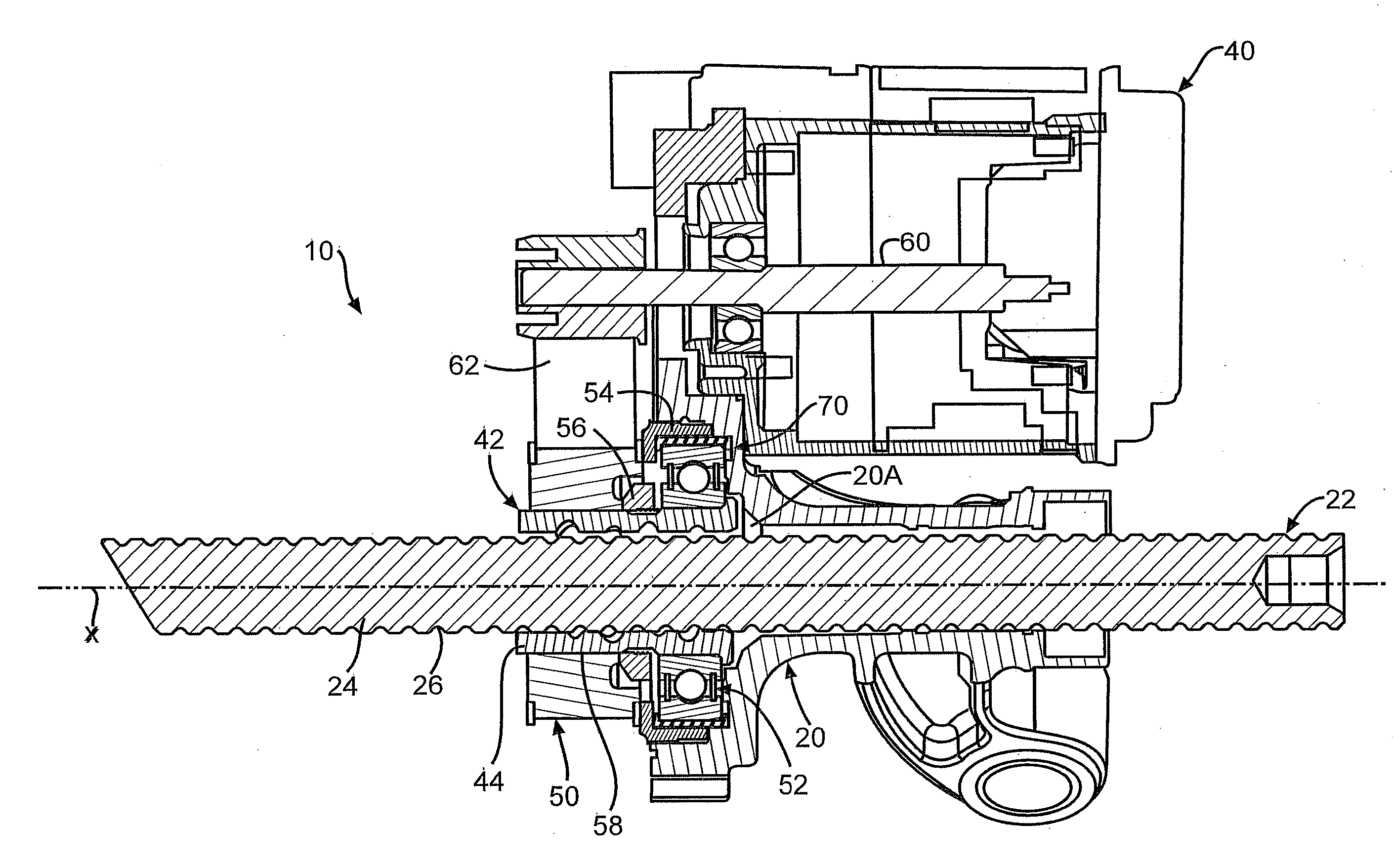
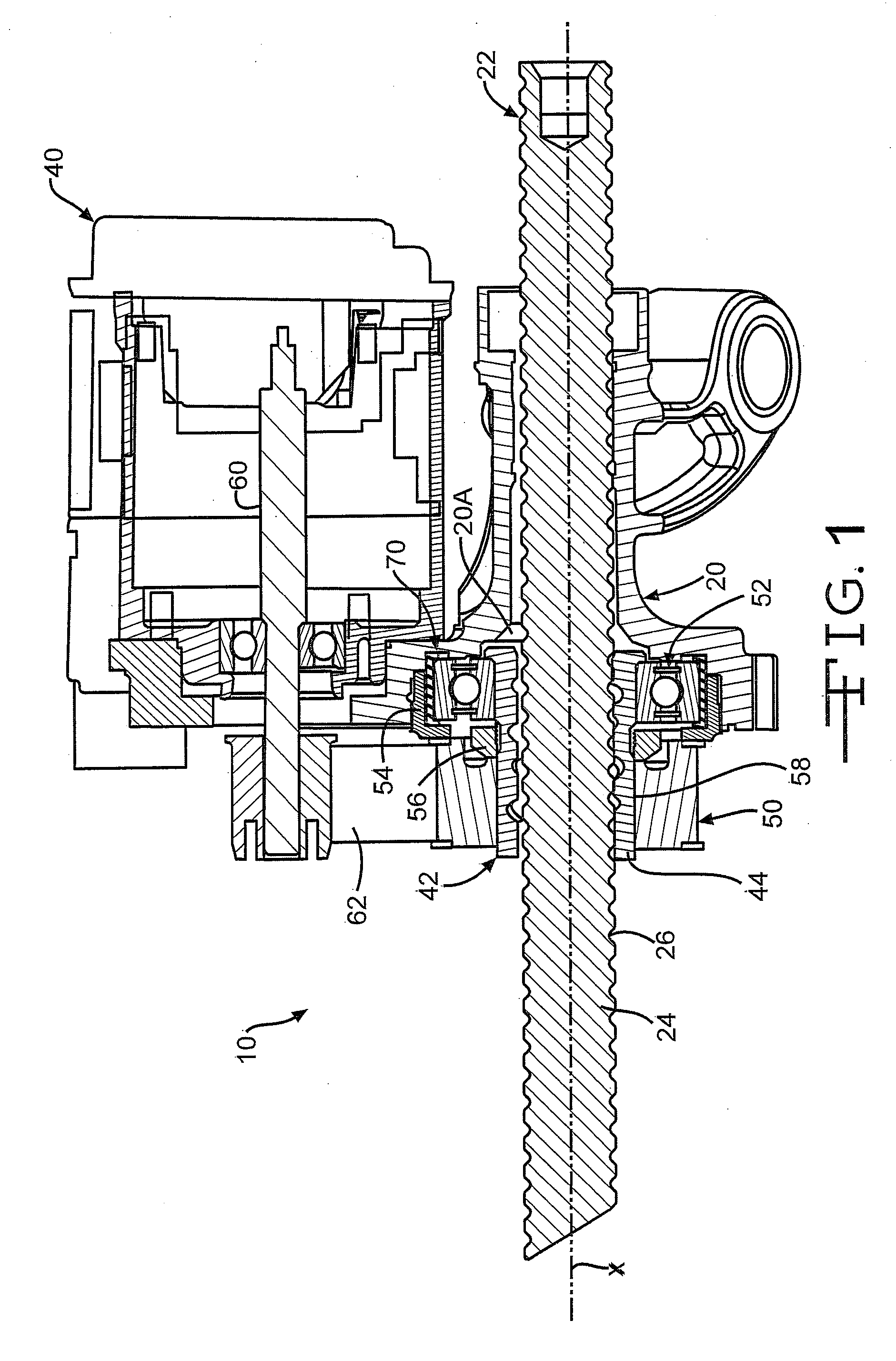
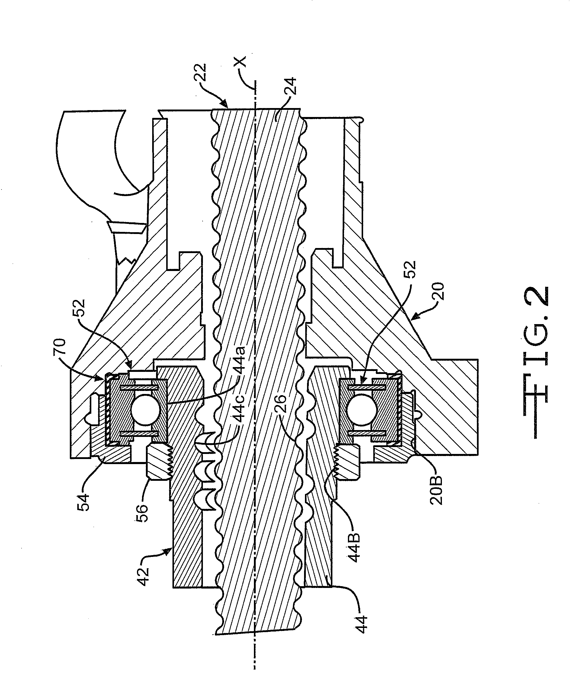
[0016]Referring now to FIGS. 1-3, there is illustrated a vehicle electric power steering assembly, indicated generally at 10, constructed in accordance with the present invention. The illustrated vehicle electric power steering assembly 10 is a vehicle electric belt driven rack drive steering assembly and is associated with the front driven wheels (not shown) of the vehicle. The general structure and operation of the electric power steering assembly 10 is conventional in the art. Thus, only those portions of the electric power steering assembly 10 which are necessary for a full understanding of this invention will be explained and illustrated in detail. Also, although this invention will be described and illustrated in connection with the particular electric power steering assembly 10 disclosed herein, it will be appreciated that this invention may be used in connection with other electric power steering assemblies. For example, the invention may be used in connection with other ele...

second embodiment

[0029]Turning now to FIG. 4 and using like reference numbers to indicate corresponding parts, there is illustrated a portion of a vehicle electric power steering assembly, indicated generally at 80, constructed in accordance with the present invention. In this embodiment, a damper 82 is provided having one or more metal plates or otherwise rigid members disposed therein, preferably disposed therein by integrally molding the plates or members therein.

[0030]In the illustrated embodiment, the damper 82 is preferably provided with at least integrally molded metal plates 84A and 86A disposed at least within a portion of one or both of a pair of sides or legs 84 and 86, respectively, thereof. Preferably, this embodiment of the damper 82 would not be molded onto the associated bearing assembly 52 but would be preferably fitted or stretched thereon prior to assembly. However, if so desired, the damper 82 may be molded onto the bearing assembly 52. Alternatively, the shape, construction and / ...

third embodiment

[0031]Turning now to FIG. 5 and using like reference numbers to indicate corresponding parts, there is illustrated a portion of a vehicle electric power steering assembly, indicated generally at 100, constructed in accordance with the present invention. In this embodiment, the vehicle electric power steering assembly 100 includes a damper or insulator, indicated generally at 101, which is operatively disposed between selected adjacent surfaces of the bearing assembly 52, the spanner nut 54 and the housing 20.

[0032]In this embodiment, the damper 101 is comprised of a pair of dampers 102 and 102′. In the illustrated embodiment, each of the pair of dampers 102 and 102′ are shown as being identical to each other; however, the construction of the pair of dampers 102 and 102′ can be different from each other if so desired. For discussion purposes, since the dampers 102 and 102′ are illustrated as being identical, only the construction of the damper 102 will be discussed below in detail. H...


PUM


Abstract

An improved structure for a rack drive assembly adapted for use in a vehicle electric power steering assembly includes a ball nut assembly operatively connected to a screw portion of a rack portion of a steering member of the power steering assembly for effecting axial movement of the steering member upon rotation of a vehicle steering wheel. According to one embodiment, the ball nut assembly includes a ball nut having an outer surface; a bearing assembly fixedly disposed in the rack housing and carried by the ball nut for rotatably supporting the ball nut assembly relative to the steering member; and a damper disposed on an outer race of the bearing assembly. The damper includes a pair of dampers disposed on the outer race of the bearing assembly, each of the dampers including at least a first member formed from a first rigid material and a second member formed from a second damping material.

Description

BACKGROUND OF THE INVENTION[0001]This invention relates in general to vehicle electric power steering assemblies and in particular to an improved rack drive assembly adapted for use in such a vehicle electric power steering assembly.[0002]One known electric power steering assembly for turning steerable wheels of a vehicle includes a ball nut for transmitting force between an axially movable rack member and an electric motor. Upon actuation of the electric motor of the power steering assembly, the ball nut is driven to rotate relative to the rack member. The rotational force of the ball nut is transmitted to the rack member by balls to drive the rack member axially. The axial movement of the rack member by the balls effects turning movement of the steerable wheels.[0003]The electric motor in the above-described electric power steering assembly can be coupled to drive the ball nut in various known methods. One such method includes a belt drive assembly wherein an output shaft of the e...

Claims


Application Information

Patent Timeline
Patent Type & Authority Applications(United States)
IPC IPC(8): B62D5/04
CPCB62D5/0448F16H25/24F16C27/066B62D5/046B60Y2306/09B60Y2304/05
Inventor BUGOSH, MARKURBACH, BRIAN
Owner TRW AUTOMOTIVE US LLC
Why Eureka
Try Eureka