Tapered brake disk

Active Publication Date: 2011-09-15
TOYOTA JIDOSHA KK +1
View PDF16 Cites 11 Cited by
  • Summary
  • Abstract
  • Description
  • Claims
  • Application Information

AI Technical Summary

Benefits of technology

[0010]According to various embodiments, an aircraft brake system comprises an aircraft rotor oriented orthogonally with respect to an axis of rotation, and an aircraft stator that nests with the aircraft rotor, where a stator friction surface is non-orthogonal to the axis of rotation. The aircraft rotor includes a rotor friction surface that is non-orthogonal to the axis of rota

Problems solved by technology

In existing brake stacks, as the actuator applies pressure to the pressure plate and compresses the brake stack, the frictional forces between the brake disks may induce unwanted vibration in the brake system.
For example, vibration levels in the brake housing, the axle, and the brake rod may reach undesirable levels during braking.
Because the friction surfaces of the brake disks are substantially parallel to each other, vibration due to disk runout may occur, such as whirl vibration and rotor cycloidal vibration.
In addition to increasing the weight of the brake system, the orifices ad

Method used


Image

  • Tapered brake disk
  • Tapered brake disk
  • Tapered brake disk

Examples


Example

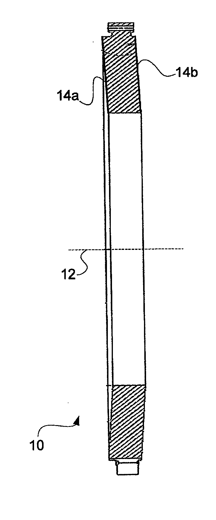
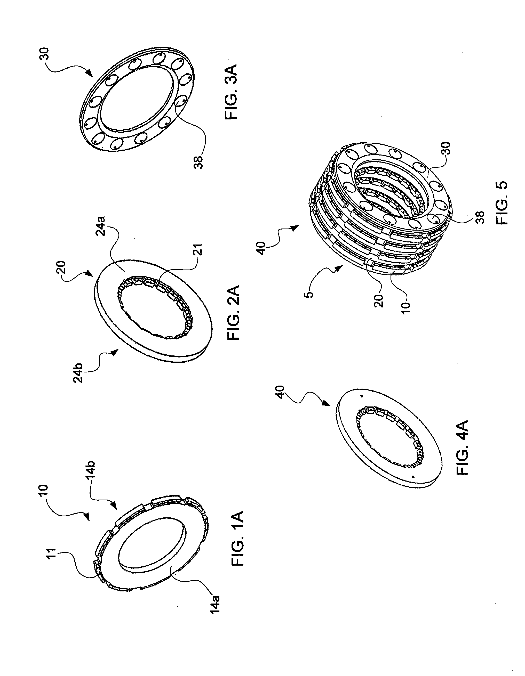
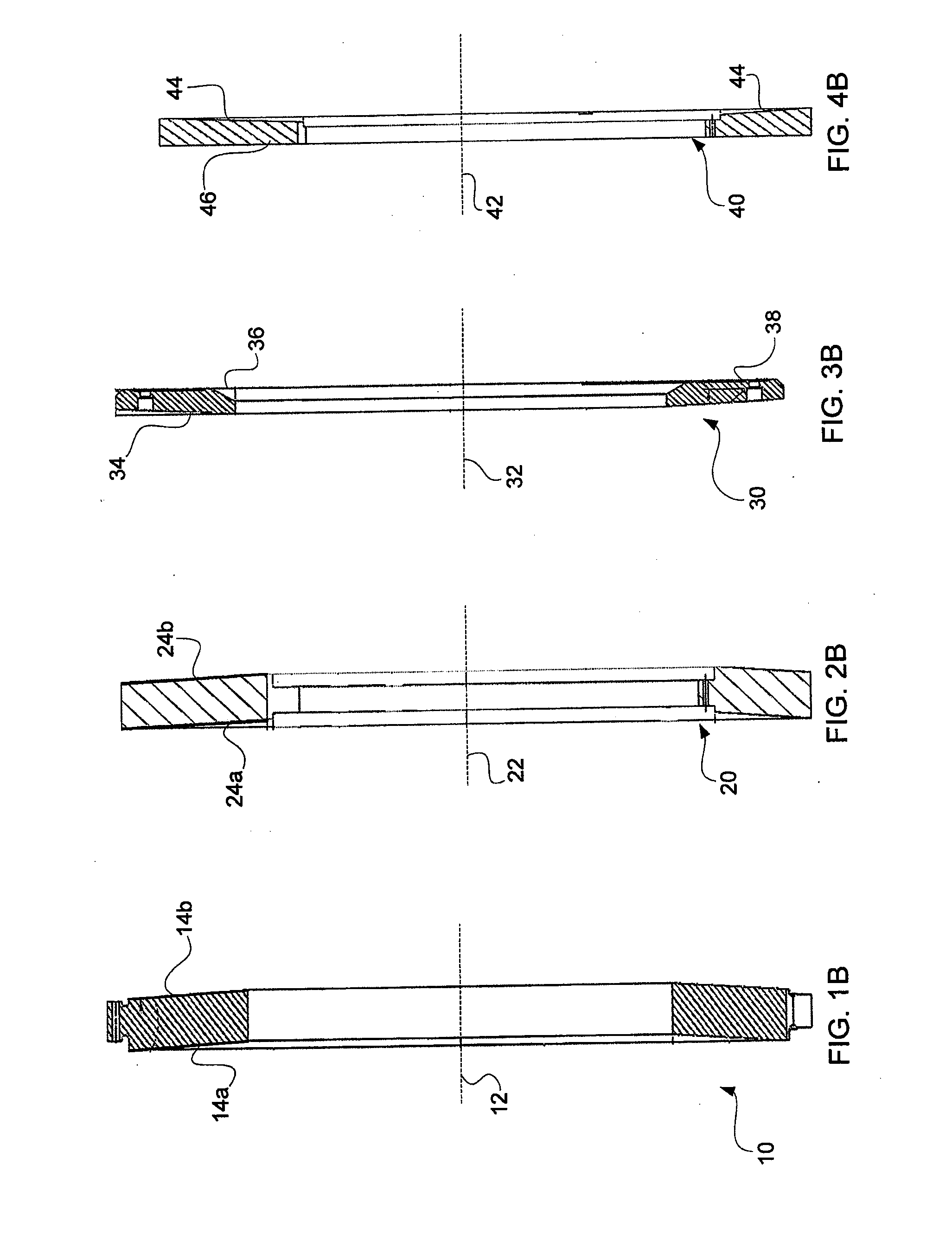
[0024]The detailed description of various embodiments herein makes reference to the accompanying drawing figures, which show various embodiments and implementations thereof by way of illustration and its best mode, and not of limitation. While these embodiments are described in sufficient detail to enable those skilled in the art to practice the embodiments, it should be understood that other embodiments may be realized and that mechanical and other changes may be made without departing from the spirit and scope of the invention. Furthermore, any reference to singular includes plural embodiments, and any reference to more than one component may include a singular embodiment.

[0025]Also, any reference to attached, fixed, connected or the like may include permanent, removable, temporary, partial, full and / or any other possible attachment option. Additionally, any reference to without contact (or similar phrases) may also include reduced contact or minimal contact. Finally, though the v...


PUM


Abstract

A brake stack comprises a stator having an annular, inner periphery section disposed substantially along a first radial plane extending normal to an axis of a wheel, and a stator side wall having a first stator contact surface, the first stator contact surface including a sloped portion which deviates away from the radial plane defined by the annular, inner periphery section. The brake stack further comprises a rotor having an annular, outer periphery section disposed substantially along a second radial plane extending normal to the axis of the wheel, and a rotor side wall having a first rotor contact surface shaped complementary to the first stator contact surface, wherein the stator and the rotor are interleaved.
A brake disk may comprise a first radius of a friction surface at a first axial position and a second radius of the friction surface at a second axial position, where the first radius is different than the second radius. The brake disk may further comprise an axis of rotation orthogonal to a plane of rotation, wherein the brake disk rotates substantially in the plane of rotation, and wherein the friction surface is at an acute angle to the plane of rotation.
An aircraft brake system comprises an aircraft rotor oriented orthogonally with respect to an axis of rotation and an aircraft stator configured to nest with the aircraft rotor, where a stator friction surface is non-orthogonal to the axis of rotation. The aircraft brake system may further comprise a pressure plate and an end plate configured to nest with the aircraft rotor and/or aircraft stator, and an actuator may be utilized to effectuate braking of the aircraft braking system.

Description

FIELD OF INVENTION[0001]This invention generally relates to a tapered brake disk, and more particularly, to rotors and stators having friction surfaces configured to cause the rotors and stators to remain substantially on center during braking.BACKGROUND OF THE INVENTION[0002]Aircraft wheel and brake systems generally include a non-rotatable wheel support, a wheel rotatably mounted to the wheel support, and a brake heat sink (or brake stack) having alternating brake disks (e.g., rotors and stators) mounted with respect to the wheel support and wheel for axial movement with respect to the wheel. In general, each rotor disk is coupled to the wheel for rotation with the wheel about a wheel rotation axis, and each stator disk is coupled to the wheel support in a non-rotatable manner. An end plate is located at one end of the brake stack, and a pressure plate is located at an opposite end of the brake stack. The rotors and stators are interleaved between the end plate and the pressure pl...

Claims


Application Information

Patent Timeline
IPC IPC(8): B64C25/42F16D65/12
CPCB64C25/44F16D65/0006F16D2065/1368F16D2065/024F16D65/12
Inventor ENRIGHT, JOHN JOSEPH
Owner TOYOTA JIDOSHA KK
Why Eureka
Try Eureka