Two-way generation tidal power plant with bypasses

a technology of tidal power plants and bypasses, which is applied in the direction of electric generator control, machines/engines, mechanical equipment, etc., can solve the problems of inability to work, inability to meet the needs of users, and the plant according to the patent gb 2436857 is more expensive than the one cited in gb 2436857, so as to increase the daily energy output

Inactive Publication Date: 2011-09-15
GOKHMAN ALEXANDER
View PDF1 Cites 7 Cited by
  • Summary
  • Abstract
  • Description
  • Claims
  • Application Information

AI Technical Summary

Problems solved by technology

Le Rance in France was built as TWPP plant with barrage and two-way hydraulic turbines, however it cannot work during flood.
It is obvious that a plant according to the Patent GB 2436857 is more expensive than an ebb generation tidal power plant having the same number of units.
For Kt=200 (the value accepted for the Cardiff-Weston barrage) this two-way plant gives only 5.8% more energy than the ebb plant with an increase in capital investment for construction around 10% and, therefore, from an economical point of view is not acceptable.
For Kt≧300 the increase in energy is not sufficient to overcome the increase of construction cost, because the power house represents the predominant expense which grows proportionally to Kt.

Method used


Image

  • Two-way generation tidal power plant with bypasses
  • Two-way generation tidal power plant with bypasses
  • Two-way generation tidal power plant with bypasses

Examples


Embodiment Construction

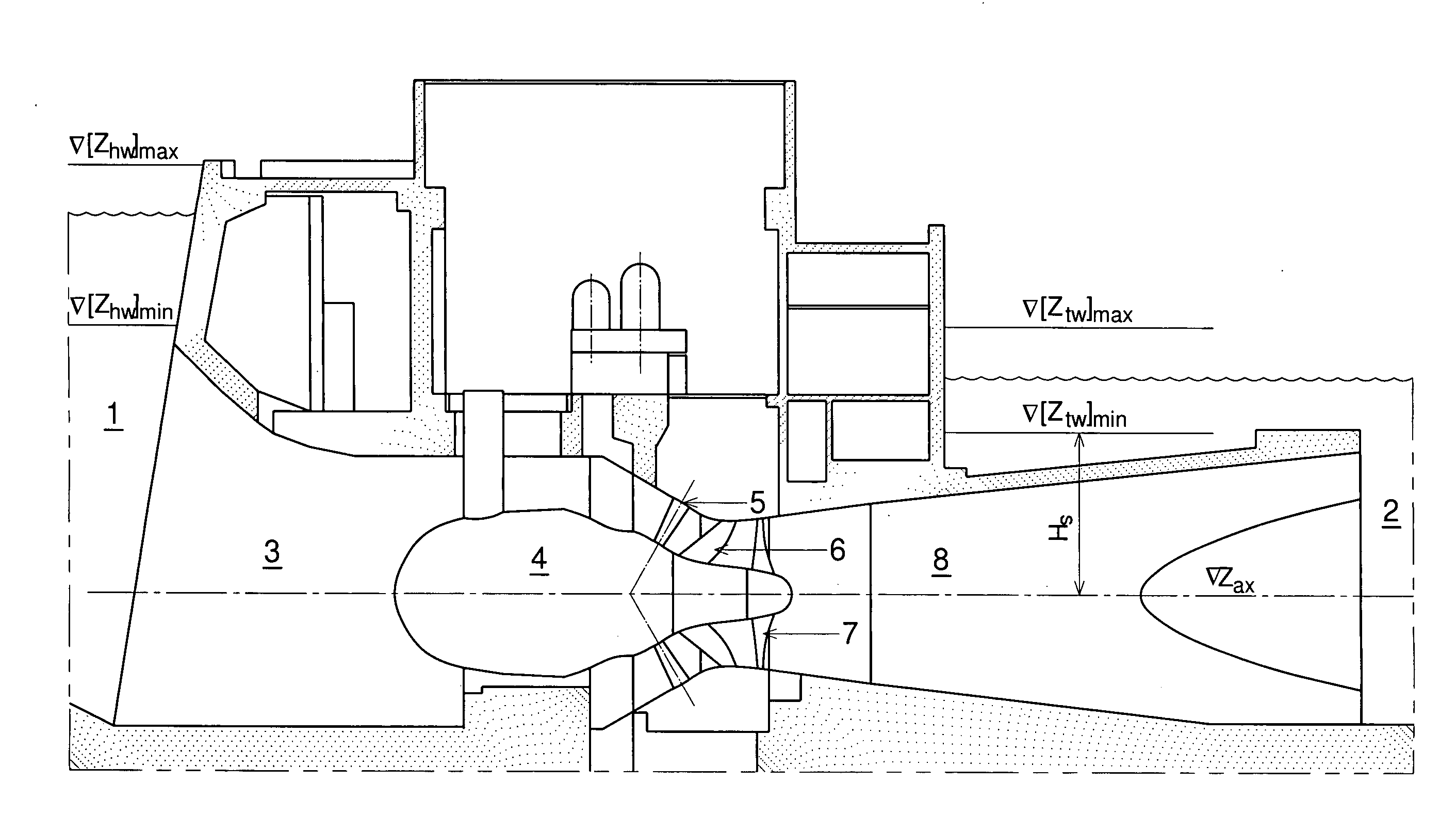
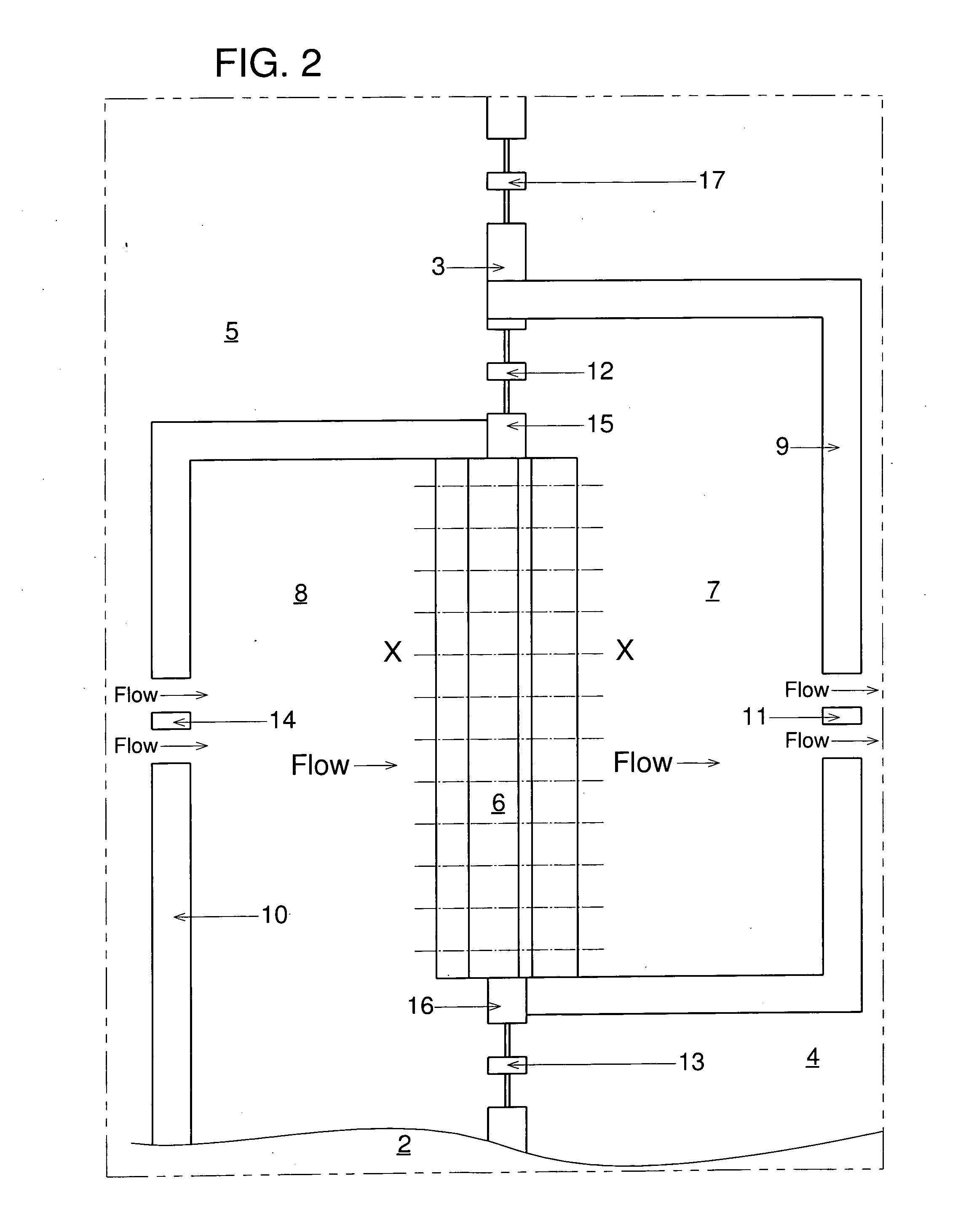
[0034]Referring now to FIG. 1, a two-way generation tidal power plant with bypasses participating in generation and with one-way turbines is shown. The tidal power plant comprises the main barrage 3 and the power house 6 with one-way turbines between the bay shores 1 and 2. The power house 6 is located at the shore 2. The head reservoir 8 is formed by the head barrage 10 located in the basin 5, the power house 6, a part of the main barrage 16 located between the power house 6 and the shore 2, and the shore 2 between the head barrage 10 and a part of the main barrage 16. The tail reservoir 7 is formed by the tail barrage 9 located in the outer bay 4, the power house 6, and a part of the main barrage 15 located between the power house 6 and the tail barrage 9. There are the following sets of sluices:

[0035]sluices 14 located at the head barrage 10 and connecting the head reservoir 8 with the basin 5,

[0036]sluices 13 located at the part of the main barrage 16 and connecting the head res...


PUM


Abstract

The invention is a two-way generation tidal power plant with bypasses participating in generation. The preferred embodiment of such a tidal power plant has a power house with one-way turbines and additional head and tail reservoirs formed by additional barrages in the basin and the outer bay. The purpose of this invention is to increase the energy production per each tidal cycle and the water volume used for it. The closer this water volume to the water volume filling and emptying the basin under natural conditions without barrage, the smaller is the environmental impact of the tidal power plant. In order to achieve this, the main barrage is equipped with bypasses, the sluices passing water during the final phases of the ebb and the flood generations in parallel to the power house turbines and having a discharge capacity up to 15 times higher than the discharge capacity of the turbines.

Description

BACKGROUND OF THE INVENTION[0001]This invention relates to tidal power plants (TPP) More specifically, the invention relates to two-way generation tidal power plants with a barrage equipped with one-way hydraulic turbines (TWTPP).[0002]All operating TPP with a barrage generate the power only during ebb. Le Rance in France was built as TWPP plant with barrage and two-way hydraulic turbines, however it cannot work during flood. So at present time still is very important to develop TPP generating the power during ebb and flood. Taking into the account the experience of Le Rance it is easy to see that only TWTPP with a barrage equipped with one-way hydraulic turbines can generate the power during ebb and flood.[0003]Any two-way generation tidal power plant with a barrage and a power house with one-way hydraulic turbines connected to electric generators must have head and tail reservoirs located at the basin and the outer bay, or vice versa, formed by auxiliary barrages and parts of the ...

Claims


Application Information

Patent Timeline
Patent Type & Authority Applications(United States)
IPC IPC(8): F03B13/26
CPCF03B13/105Y02E10/38Y02E10/28F03B13/268Y02E10/30Y02E10/20
Inventor GOKHMAN, ALEXANDER
Owner GOKHMAN ALEXANDER
Why Eureka
Try Eureka