
Tracks for all-terrain vehicles

a technology for all-terrain vehicles and tracks, applied in the direction of driving chains, hinges, transportation and packaging, etc., can solve the problems of difficult pre-stressing, difficult to ensure pre-stressing, and reduced surface area of track shoes with the ground, so as to reduce the wear of track shoes

Active Publication Date: 2011-09-15
NEXTER SYST SA
View PDF6 Cites 20 Cited by
  • Summary
  • Abstract
  • Description
  • Claims
  • Application Information

AI Technical Summary

Benefits of technology

[0026]The aim of the invention is to propose a new track concept that enables such drawbacks to be overcome and namely a track whose contact surface with the ground by unit length is increased, thereby reducing the wear on the track shoes.
[0027]The track according to the invention is of simple design and incorporates fewer parts than known tracks. It may be assembled and disassembled in the field without the need for specific tooling.
[0028]Lastly, the track according to the invention has a constant distance between pins that ensure the regular winding on the drive gears, thereby significantly reducing noise and vibrations.

Problems solved by technology

Indeed, such frictions would lead to the premature wear of the pins causing fractures.
Firstly we note that it is formed of a large number of parts. The assembly and disassembly of the links is, furthermore, complicated.
This pre-stressing is difficult to ensure in the field when the crew does not have the specific tooling.
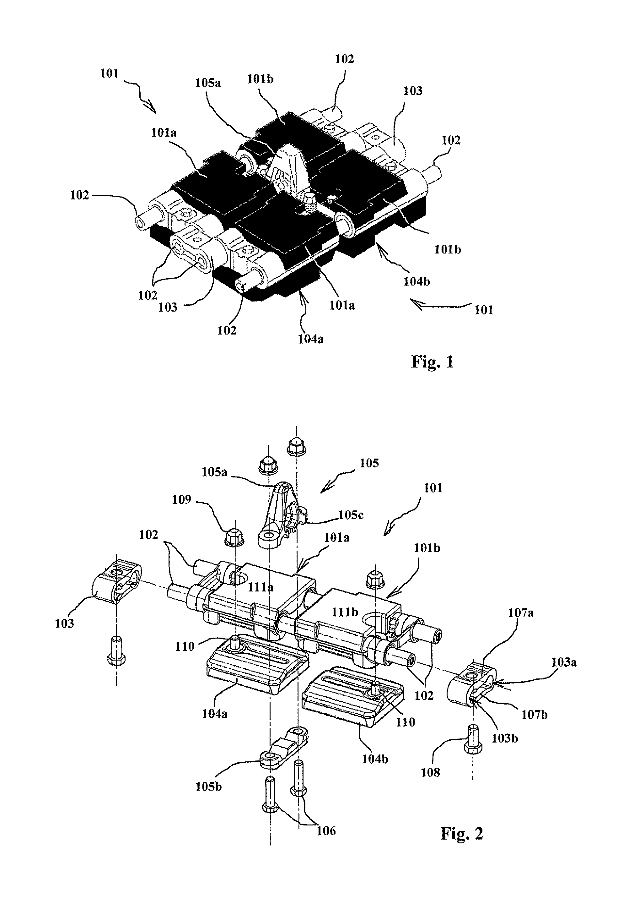
Frequent assembly and disassembly causes the premature wear of the connectors 103 thereby forming a weak point in the tracks.
The contact surface of the track shoes with the ground is relatively reduced, which results in a relatively rapid wear of the shoes which come into contact with the ground in an abrupt manner, link by link.
Lastly, with such links, it is not possible to obtain a constant distance between the pins 102 of the links.
The unequal distance between the pins results in a winding of the track that is by surges and substantial vibrations that are communicated to the ground and to the vehicle.

Method used


Image

  • Tracks for all-terrain vehicles
  • Tracks for all-terrain vehicles
  • Tracks for all-terrain vehicles

Examples


Embodiment Construction

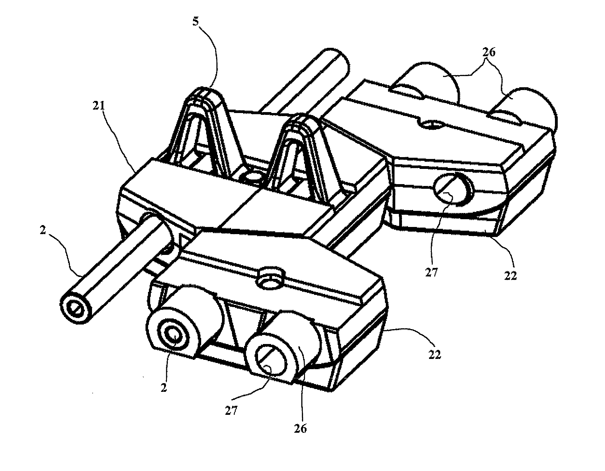
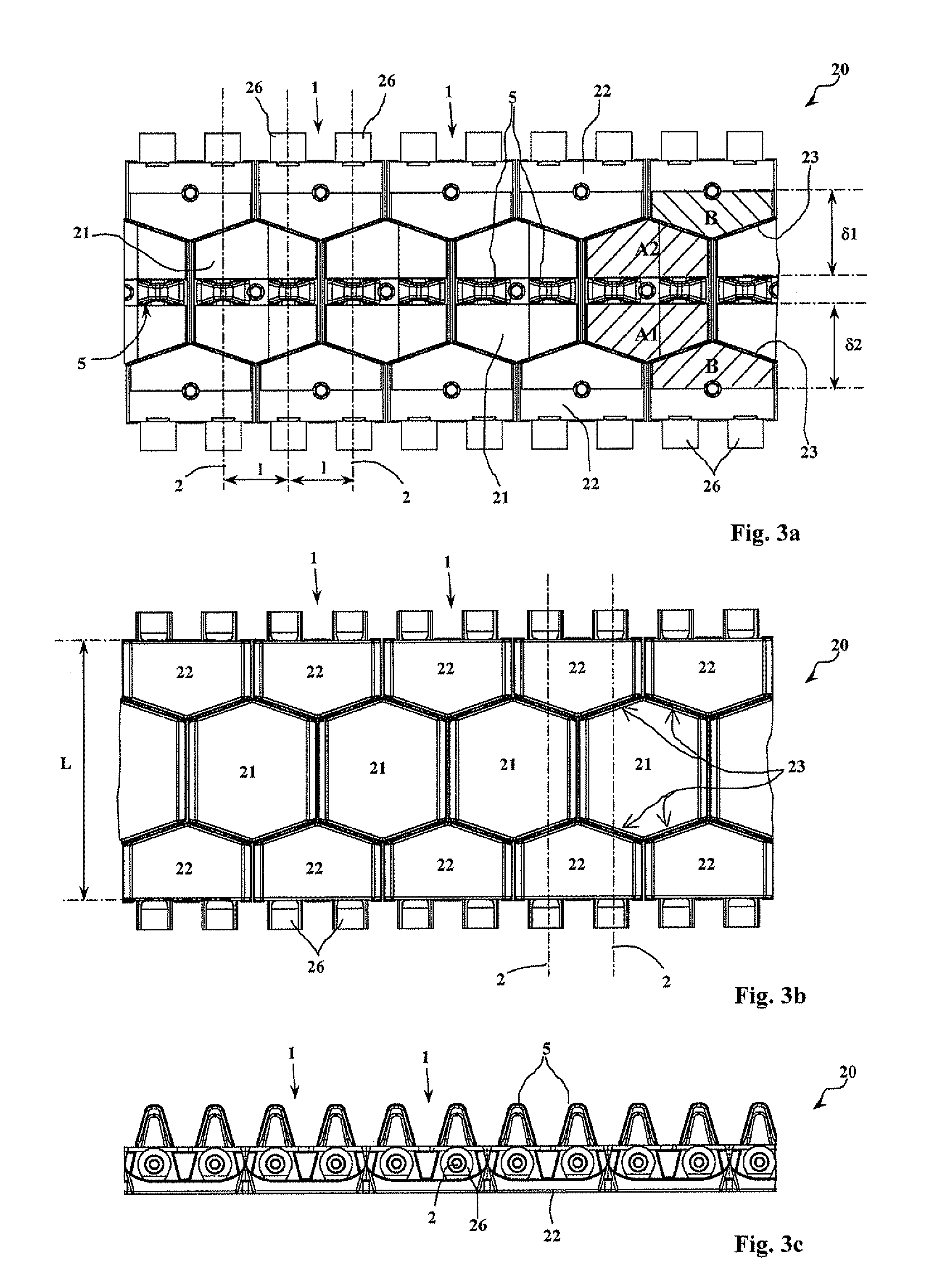
[0059]With references to FIGS. 3a to 3c, a track 20 according to the invention is formed by the assembly of links 1 which are hinged to one another so as to form a closed chain.

[0060]FIG. 3b, a top view (thus of the face of the track that is in contact with the ground), more particularly shows that the track 20 comprises several bodies equipped with a track shoe intended to come into contact with the ground. The track 20 thus incorporates a row of median bodies 21 and two rows of lateral bodies 22.

[0061]The row of median bodies 21 is arranged to be longitudinally offset with respect to the rows of lateral bodies 22. Each median body 21 is thus placed staggered between four lateral bodies 22.

[0062]We see in FIGS. 3a and 3b that the median bodies 21 are globally hexagonal in shape, the lateral bodies 22 having, furthermore, profiles 23 that correspond to those of the median bodies facing which they are positioned. The space between the median bodies and the lateral bodies is thereby r...


PUM


Abstract

A track for an all-terrain vehicle, and namely for an armored vehicle, comprising links hinged together so as to form a closed chain, each link carrying at least one body equipped with a track shoe intended to come into contact with the ground, track wherein it incorporates a row of median bodies that is arranged so as to be longitudinally offset with respect to the row of lateral bodies, each median body being thus positioned staggered between four lateral bodies, each median body being further hinged, by means of at least two parallel pins, to four lateral bodies, that is to say two lateral bodies from each lateral row, the pins being positioned at an equal distance from one another.

Description

BACKGROUND OF THE INVENTION[0001]1. Field of the Invention[0002]The technical scope of the invention is that of tracks for all-terrain vehicles and in particular for armored vehicles.[0003]2. Description of the Related Art[0004]Such tracks are well known to some skilled in the art. They are constituted by an assembly of links, hinged together, forming a closed chain winding around crown gear linked to the vehicle's motorization.[0005]FIG. 1 thus shows an assembly of two links of a track according to prior art. FIG. 2 shows an exploded view of a link of such a track.[0006]The parts shown in black in FIG. 1 are made of rubber.[0007]We can see in FIG. 1 that the links 101 are not linked directly to one another. They are joined by means of pins 102 and connectors 103.[0008]Thus, each link 101 incorporates two parallel drill holes that each receives a pin 102. The link is, furthermore, formed of two identical bodies 101a and 101b. Each link 101 is fastened to another link by means of con...

Claims


Application Information

Patent Timeline
Patent Type & Authority Applications(United States)
IPC IPC(8): B62D55/21
CPCB62D55/202B62D55/20B62D55/26B62D55/21
Inventor BONNETAIN, FREDERICGENDRY, YANN
Owner NEXTER SYST SA
Learn More