Electric rotating machine

a technology of rotating machines and rotating shafts, which is applied in the direction of dynamo-electric machines, electrical apparatus, magnetic circuit shapes/forms/construction, etc., can solve the problems of increasing manufacturing costs, difficult to effectively transmit the heat generated by the stator coil to the stator core, and difficult to spread the cooling oil over the entire axial length of each gap between the insulator and the stator core, so as to achieve effective transmission of heat and reduce heat resistance between the stator core and

Inactive Publication Date: 2011-09-15
NIPPON SOKEN +1
View PDF7 Cites 12 Cited by
  • Summary
  • Abstract
  • Description
  • Claims
  • Application Information

AI Technical Summary

Benefits of technology

[0016]With the above configuration, the coolant can flow from the outside coolant passage into each of the slots of the stator core via the corresponding inside coolant passages. Consequently, the heat resistance between the stator core and the stator coil can be reduced, thereby more effectively transmitting the heat generated by the stator coil to the stator core. As a result, it is possible to suppress the increase in the resistance of the stator coil due to the heat generated by the stator coil, thereby ensuring high efficiency of the electric rotating machine. Moreover, it is also possible to prevent the insulating coat of the stator coil from being damaged by the heat generated by the stator coil. Furthermore, since the inside coolant passages are formed without making the magnetic steel sheets discontinuous in the circumferential direction, it is possible to ensure the strength of each of the magnetic steel sheets and thus the strength of the entire stator core.
[0018]With the above configuration, if an insulator is interposed between the stator coil and the stator core in partial contact with the internal walls of the magnetic steel sheets, it is possible for the coolant to flow through the grooves to occupy the entire axial length of each of the gaps between the insulator and the internal walls of the magnetic steel sheets. As a result, the heat resistance between the stator core and the stator coil can be reduced, thereby more effectively transmitting the heat generated by the stator coil to the stator core.

Problems solved by technology

However, due to manufacturing tolerances, the stator core may have uneven internal walls which define the slots of the stator core.
In this case, if the insulator is disposed in partial contact with the internal walls of stator core, it will be difficult for the cooling oil to spread over the entire axial length of each of the gaps between the insulator and the stator core.
As a result, it will be difficult for the heat generated by the stator coil to be effectively transmitted to the stator core.
Consequently, the manufacturing cost will be increased.

Method used


Image

  • Electric rotating machine
  • Electric rotating machine
  • Electric rotating machine

Examples


first embodiment

[First Embodiment]

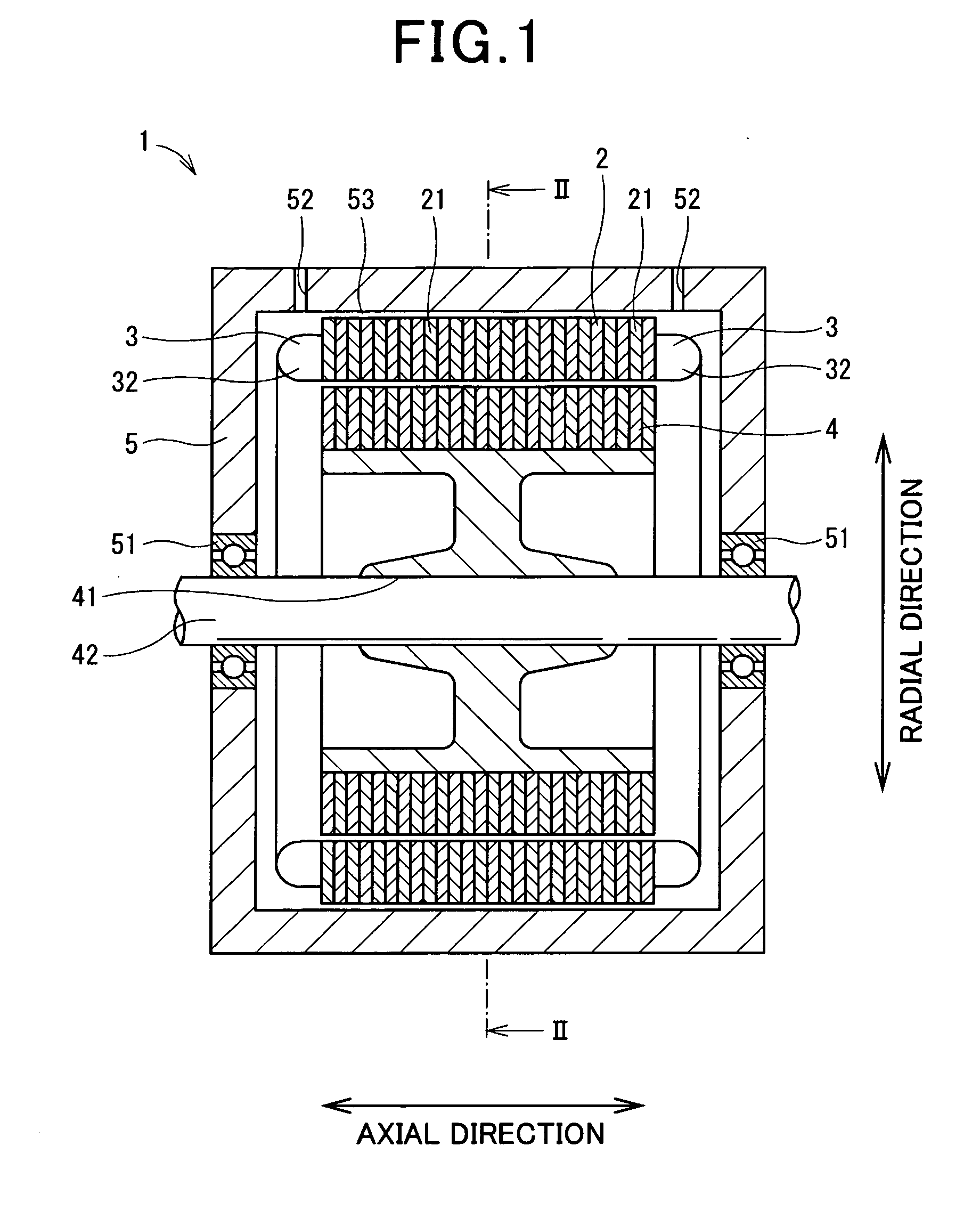
[0036]FIG. 1 shows the overall configuration of an electric rotating machine 1 according to the first embodiment of the invention.

[0037]In the present embodiment, the electric rotating machine 1 is configured as a brushless motor for use in, for example, a motor vehicle. As shown in FIG. 1, the electric rotating machine 1 includes a stator, a rotor 4, and a housing 5. The stator includes a stator core 2, a stator coil 3, and an insulator 31.

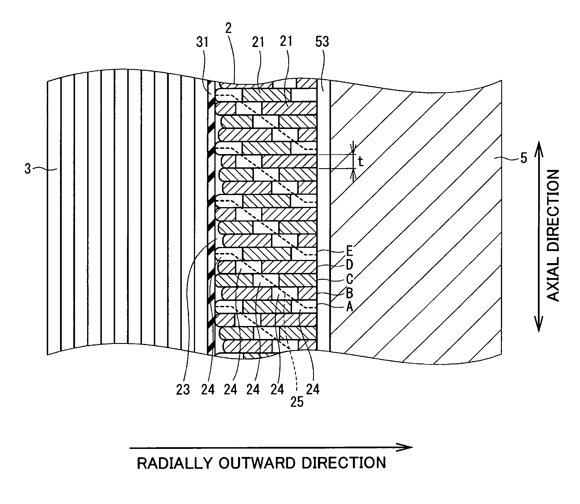
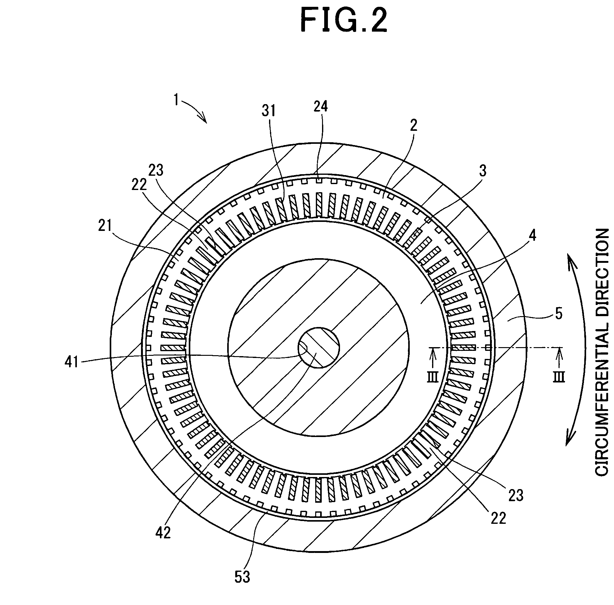
[0038]Referring to FIGS. 1 and 2, the stator core 2 is formed by laminating a plurality of magnetic steel sheets 21 and has a hollow cylindrical shape. The stator core 2 has a plurality of stator teeth 22 extending in the axial direction and a plurality of slots 23 each of which is formed between one circumferentially-adjacent pair of the stator teeth 22. More specifically, the slots 23 are formed in the radially inner surface of the stator core 2 and spaced by the stator teeth 22 in the circumferential direction of the stator c...

second embodiment

[Second Embodiment]

[0078]FIGS. 10-12 show the configuration of a stator according to the second embodiment of the invention.

[0079]In the present embodiment, as shown in FIGS. 10-12, in those internal walls of the magnetic steel sheets 21 which define the slots 23 of the stator core 2, there are formed grooves 26 that extend in the axial direction of the stator core 2.

[0080]Moreover, in the present embodiment, each of the grooves 26 has a substantially semicircular cross section perpendicular to the axial direction of the stator core 2. The magnetic steel sheets 21 also have rounded edge portions 27 that are respectively formed at axial ends of the internal walls of the magnetic steel sheets 21. Further, the radius r of the cross sections of the grooves 26 is set to be less than the radius R of the rounded edge portions 27 of the magnetic steel sheets 21.

[0081]In addition, the grooves 26 may be formed, for example by grinding, in the respective magnetic steel sheets 21 before laminat...


PUM

PropertyMeasurementUnit
dimensionsaaaaaaaaaa
widthaaaaaaaaaa
thicknessaaaaaaaaaa

Abstract

An electric rotating machine includes a stator, a rotor, and a housing. The stator includes a stator core and a stator coil formed by laminating magnetic steel sheets. Each of the magnetic steel sheets has through-holes that are formed to penetrate the magnetic steel sheet in the axial direction of the stator core. All of the magnetic steel sheets are divided into groups each of which includes axially-adjacent n of the magnetic steel sheets, where n is an integer not less than 2. For each of the groups, corresponding n of the through-holes of the n magnetic steel sheets of the group communicate with one other to form an inside coolant passage. The inside coolant passage fluidically connects an outside coolant passage, which is formed between the housing and the radially outer surface of the stator core, with a corresponding one of the slots of the stator core.

Description

CROSS-REFERENCE TO RELATED APPLICATION[0001]This application is based on and claims priority from Japanese Patent Application No. 2010-55468, filed on Mar. 12, 2010, the content of which is hereby incorporated by reference in its entirety into this application.BACKGROUND[0002]1. Technical Field[0003]The present invention relates to electric rotating machines that are used in, for example, motor vehicles as electric motors and electric generators.[0004]2. Description of the Related Art[0005]Conventionally, electric rotating machines, which are used in, for example, motor vehicles as electric motors and electric generators, generally include a stator and a rotor. The stator includes a hollow cylindrical stator core, a stator coil, and an insulator. The stator core is formed by laminating a plurality of magnetic steel sheets and has a plurality of slots that are formed in the radially inner surface of the stator core and spaced in the circumferential direction of the stator core. The s...

Claims


Application Information

Patent Timeline
Patent Type & Authority Applications(United States)
IPC IPC(8): H02K9/19
CPCH02K1/20
Inventor UCHIYAMA, KAZUNORIHAKAMADA, NAOKISEGUCHI, MASAHIRO
Owner NIPPON SOKEN
Why Eureka
Try Eureka