Battery charger and method for collecting maximum power from energy harvester circuit

a technology of energy harvester circuit and battery charger, which is applied in the direction of electric variable regulation, process and machine control, instruments, etc., can solve the problems of reducing the amount of power transferred, wasting corresponding power, and inability to convert into suitable output voltage and output current, etc., to achieve the maximum power point tracking of an energy harvester, and simple economic techniqu

Active Publication Date: 2011-09-15
TEXAS INSTR INC
View PDF11 Cites 54 Cited by
  • Summary
  • Abstract
  • Description
  • Claims
  • Application Information

AI Technical Summary

Benefits of technology

[0020]It is an object of the invention to provide a simple, economical t

Problems solved by technology

Therefore, if the value of Vout is too high, the current generated by solar harvester 2-3 is wasted.
Thus, if the value of Vout is too low, the full amount of available harvested power (Vout×Iout) is not being made available at the output of solar cell harvester 2-3, and if the value of Vout is high enough that some or all of the generated current IPH is flowing through diode D to ground, then the corresponding power is wasted and cannot be converted into a suitable output voltage and output current for charging battery 6.
The amount of power available from the harvesters of FIGS. 1-3 usually is small and unpredictable, so the intermediate energy storage (e.g., lithium batteries or

Method used


Image

  • Battery charger and method for collecting maximum power from energy harvester circuit
  • Battery charger and method for collecting maximum power from energy harvester circuit
  • Battery charger and method for collecting maximum power from energy harvester circuit

Examples


Embodiment Construction

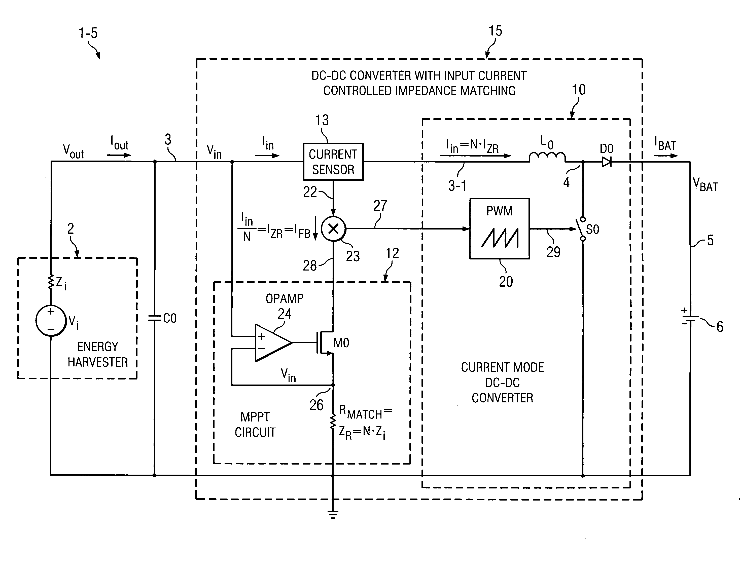
[0046]FIG. 4 shows an energy harvesting system 1-4 in which the output of energy harvester 2 is coupled by a DC-DC converter or battery charger 15 to battery 6. DC-DC converter 15 delivers a current IBAT and corresponding voltage VBAT to battery 6 via conductor 52. Energy harvester 2 is modeled as a voltage source Vi coupled between ground and one terminal of an internal impedance Zi of energy harvester 2. The other terminal of internal impedance Zi is connected by conductor 3 to the output of harvester 2, on which a harvester output voltage Vout is generated. A harvester output current Iout flows through conductor 3. The output 3 of energy harvester 2 is connected to the input of DC-DC converter 15 and applies an output voltage Vin via conductor 3 to the input of DC-DC converter 15 and also supplies an input current Iin to DC-DC converter 15. Thus, the output voltage Vout and output current Iout generated by harvester 2 are equal to the input voltage Vin and input current Iin, resp...


PUM


Abstract

An energy harvesting system for transferring energy from an energy harvester (2) having an output impedance (Zi) to a DC-DC converter (10) includes a maximum power point tracking (MPPT) circuit (12) including a replica impedance (ZR) which is a multiple (N) of the output impedance. The MPPT circuit applies a voltage across the replica impedance that is equal to an output voltage (Vin) of the harvester to generate a feedback current (IZR) which is equal to an input current (Iin) received from the harvester, divided by the multiple (N), to provide maximum power point tracking between the harvester and the converter.

Description

BACKGROUND OF THE INVENTION[0001]The present invention relates generally to energy harvesting, and more particularly to circuits and methods for improving the efficiency of transferring energy from energy harvesting devices to energy storage devices and / or load devices.[0002]Recently, various very low power integrated circuits that require extremely low amounts of operating current (often referred to as “nano-power” integrated circuits) have been developed which can be powered by very small amounts of power scavenged or harvested from ambient solar, vibrational, thermal, and / or biological energy sources by means of micro-energy harvesting devices. The harvested power then usually is stored in batteries or supercapacitors. (The term “nano-power” as used herein is intended to encompass circuits and / or circuit components which draw DC current of less than roughly 1 microampere.)[0003]FIG. 1 shows an energy harvesting system 1-1 in which the output of a thermopile energy harvester 2-1 i...

Claims


Application Information

Patent Timeline
IPC IPC(8): G05F1/70
CPCG05F1/67Y02E10/58H02J7/35Y02E10/56
Inventor IVANOV, VADIM V.LINK, CHRISTIAN
Owner TEXAS INSTR INC
Why Eureka
Try Eureka