Logic built-in self-test system and method for applying a logic built-in self-test to a device under test

a logic and built-in self-testing technology, applied in the field of integrated circuits, can solve problems such as state values and pattern loss

Active Publication Date: 2011-09-15
NXP USA INC
View PDF9 Cites 22 Cited by
  • Summary
  • Abstract
  • Description
  • Claims
  • Application Information

AI Technical Summary

Problems solved by technology

The described system does not keep the application context, i.e. the state values of the bistable multivibrator circuits before receiving the described test pattern may be lost, requiring restart of the device from a random or reset state.

Method used


Image

  • Logic built-in self-test system and method for applying a logic built-in self-test to a device under test
  • Logic built-in self-test system and method for applying a logic built-in self-test to a device under test
  • Logic built-in self-test system and method for applying a logic built-in self-test to a device under test

Examples


Embodiment Construction

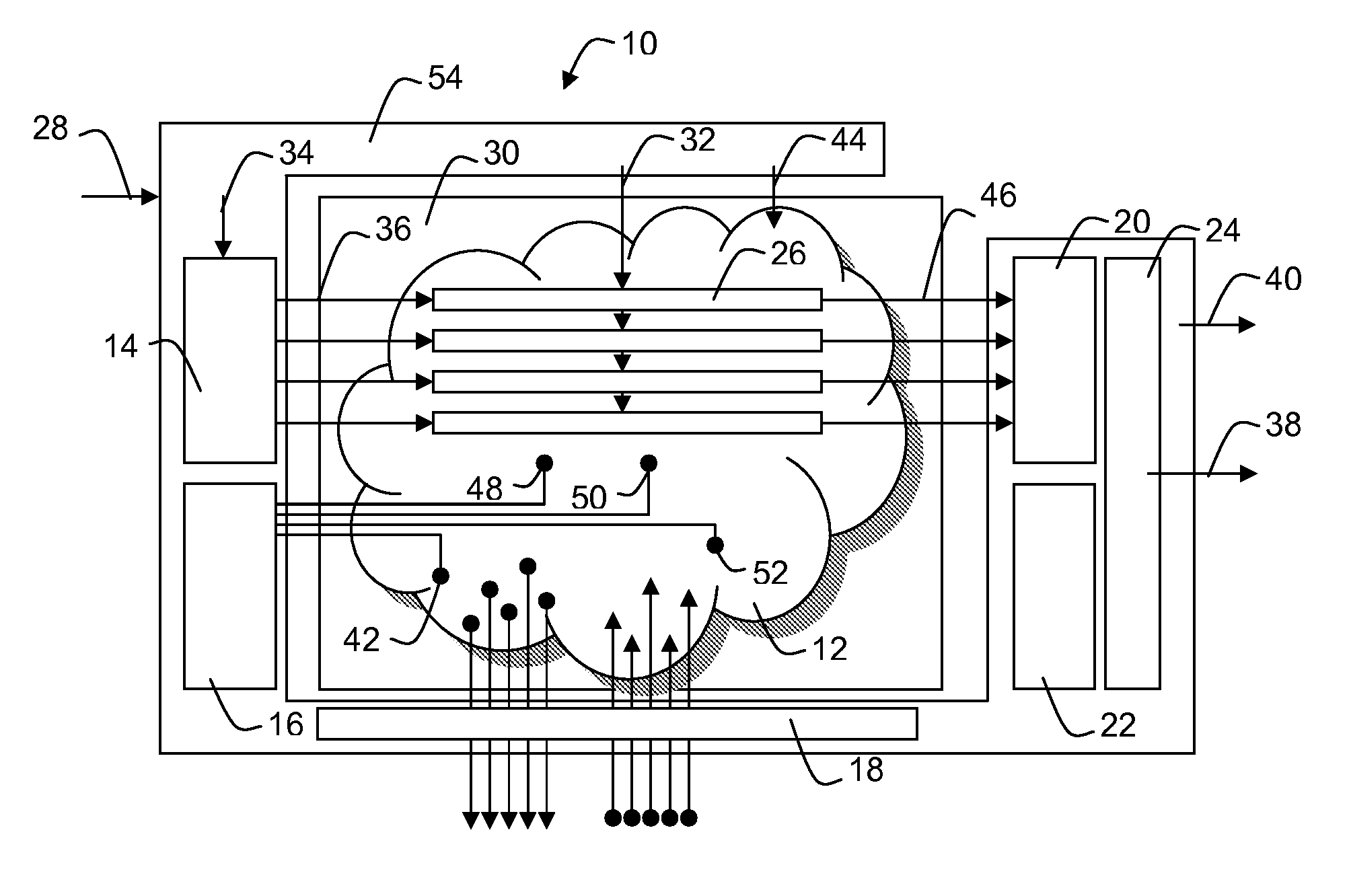
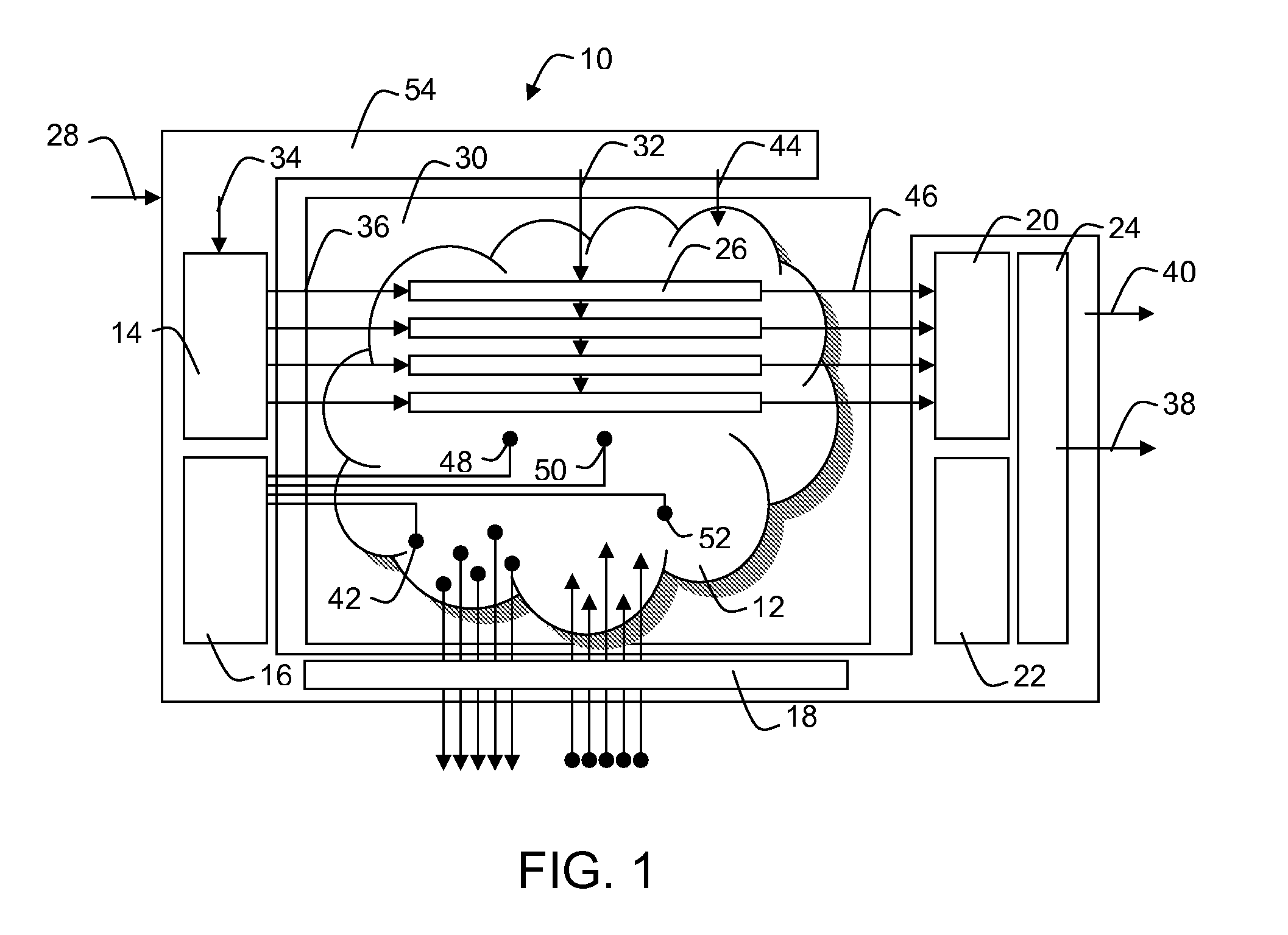
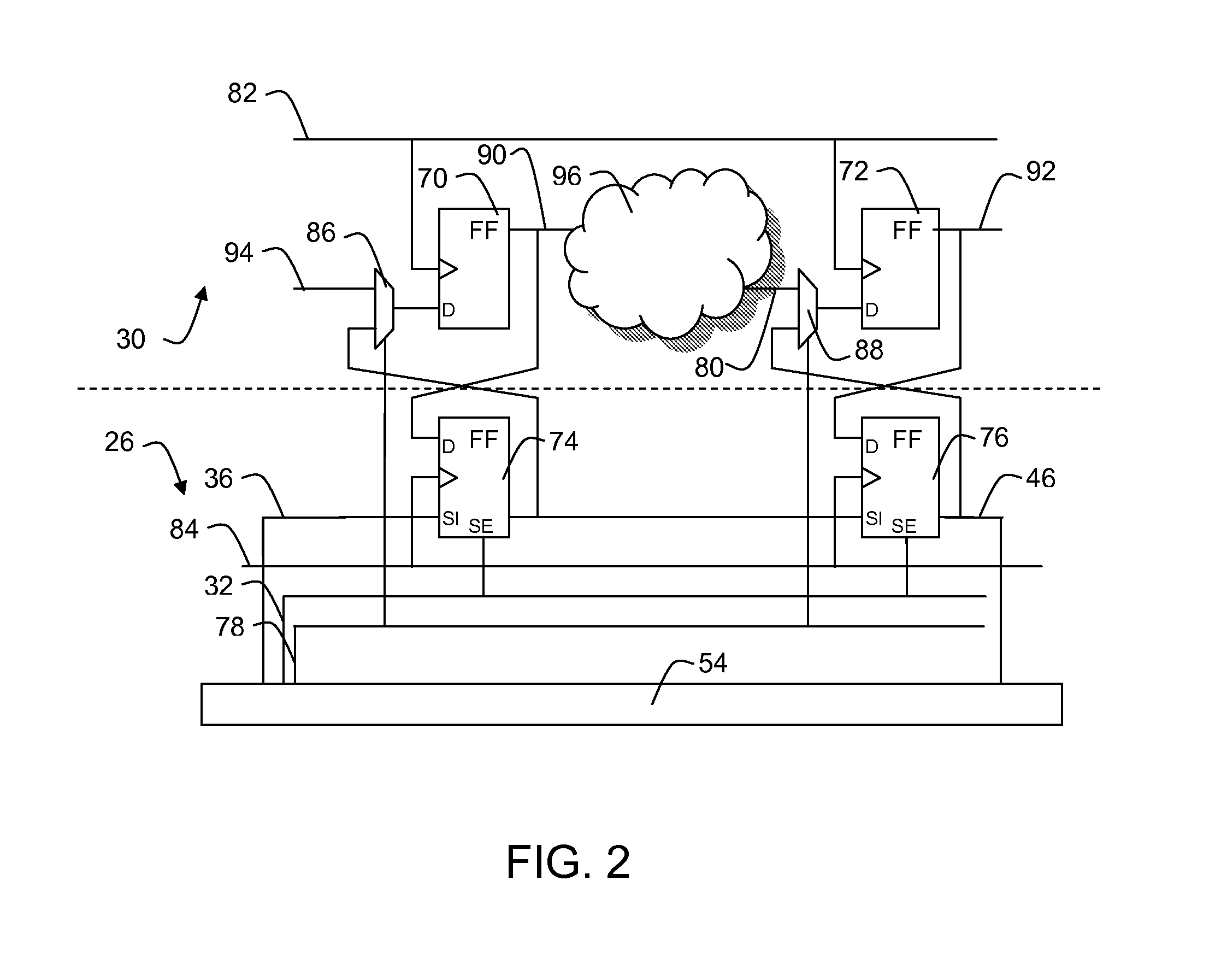
[0017]Referring to FIG. 2, a schematic diagram of an example of an embodiment of an LBIST system comprising pairs of flip-flop circuits is illustrated and described also with reference to FIG. 1. The illustrated flip-flop circuits serve as examples for bistable multivibrators. As another example, latches may be used instead. A logic built-in self test (LBIST) system is shown, comprising a device under test 30 having a first plurality of first flip-flop circuits 70, 72, an LBIST controller 54, and a second plurality of second flip-flop circuits 74, 76. Each second flip-flop circuit 74, 76 is coupled to a corresponding first flip-flop circuit 70, 72 to swap a second state value kept by the second flip-flop circuit with a first state value kept by the corresponding first flip-flop circuit depending on a first control signal 78 from the LBIST controller. The second flip-flop circuits are coupled to form one or more scan chains 26 when receiving a second control signal 32 from the LBIST ...


PUM


Abstract

A logic built-in self test (LBIST) system comprises a device under test having a first plurality of first bistable multivibrator circuits an LBIST controller, and a second plurality of second bistable multivibrator circuits. Each second bistable multivibrator circuit is coupled to a corresponding first bistable multivibrator circuit to swap a second state value kept by the second bistable multivibrator circuit with a first state value kept by the corresponding first bistable multivibrator circuit depending on a first control signal from the LBIST controller and the second bistable multivibrator circuits are coupled to form one or more scan chains when receiving a second control signal from the LBIST controller.

Description

FIELD OF THE INVENTION[0001]This invention in general relates to integrated circuits (IC) and more specifically to a system for testing the internal digital functionality of an IC.BACKGROUND OF THE INVENTION[0002]Built-in self-test of semiconductor devices in-field gains importance because of higher quality and safety requirements. Because of this, the scope of design for test (DFT) methodologies implemented during chip development extends from production test to in-field test. In order to allow for testing a certain IC device, a built-in self-test (BIST) mechanism may be implemented within an IC. A BIST mechanism is a function that verifies all or a portion of the internal functionality of the IC device under test. Logic circuitry of an IC may be tested using a logic built-in self-test (LBIST) system. LBIST of digital semiconductor devices or sub-modules of it can be used for proving defect freeness of devices in a test environment and in the field. Highest defect coverage can be a...

Claims


Application Information

Patent Timeline
Patent Type & Authority Applications(United States)
IPC IPC(8): H03K19/00
CPCG01R31/318541G01R31/31724
Inventor SCHLAGENHAFT, ROLF
Owner NXP USA INC
Why Eureka
Try Eureka