
Mutual capacitance touch screen with electrodes arranged on dual conductive material films

Inactive Publication Date: 2011-09-15
FOCALTECH SYSTEMS LTD
View PDF7 Cites 22 Cited by
  • Summary
  • Abstract
  • Description
  • Claims
  • Application Information

AI Technical Summary

Benefits of technology

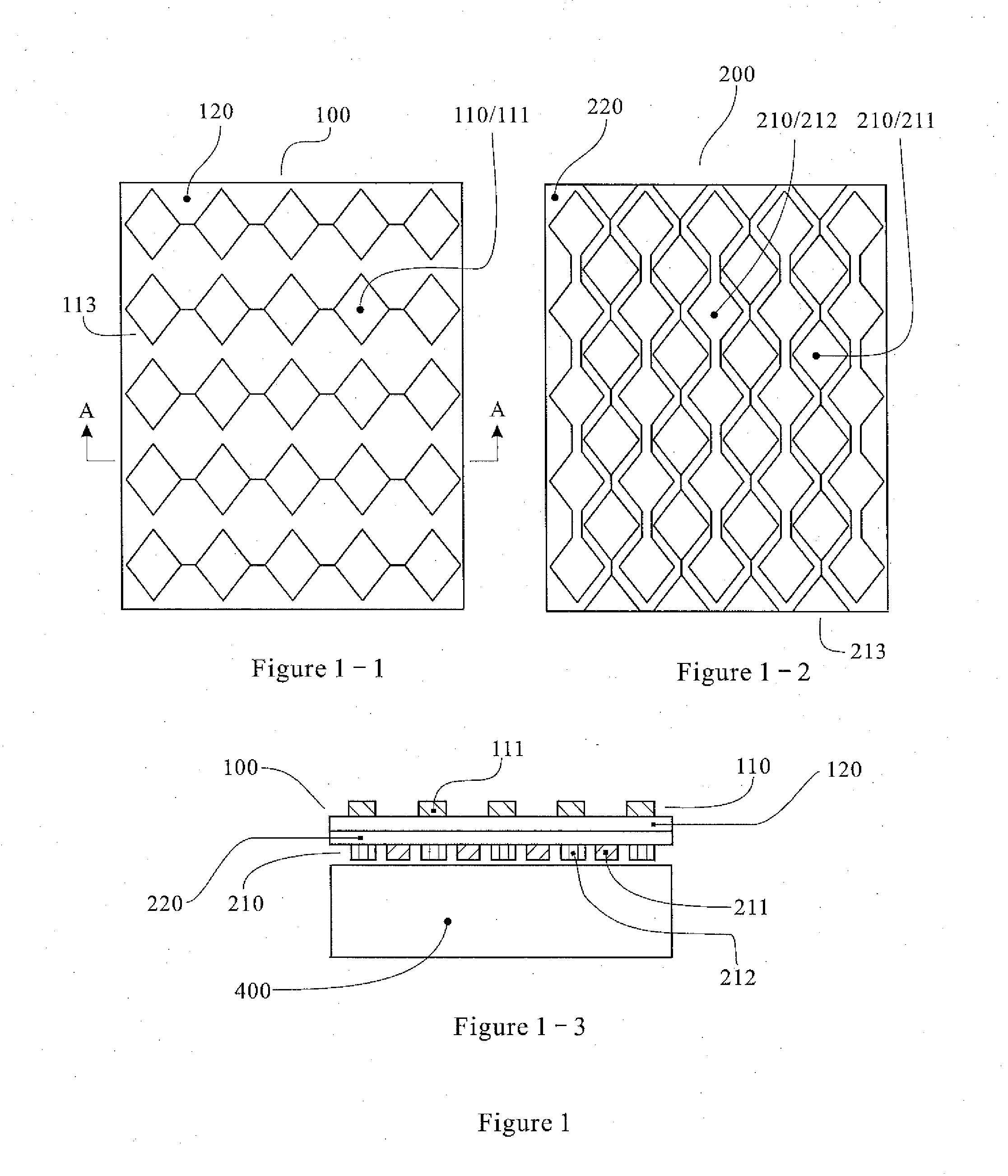
[0014]The invention ensures that the touch screen is provided with electrode films only, and the shielding electrode plates are arranged on the lower electrode film. Therefore, the invention not only effectively isolates interference from the display screen but also solves the problem that the shielding electrode film is arranged individually in the prior art to increase the thickness of the touch screen, and the invention conforms to the development trend that the touch screen shall be thinner. In addition, the shielding electrode plates and the lower electrode plates complement each other. The shielding electrode plates provided with the shielding electrode film individually are distributed to the whole electrode film. The area of the shielding electrode plates in the invention is obviously decreased, thereby reducing the manufacturing cost of the touch screen.

Problems solved by technology

However, the installation of the shielding electrode film 300′ not only increases the manufacturing cost of the mutual capacitance touch screen but also increases the thickness of the touch screen, which does not conform to the development trend that the touch screen shall be thinner.

Method used


Image

  • Mutual capacitance touch screen with electrodes arranged on dual conductive material films
  • Mutual capacitance touch screen with electrodes arranged on dual conductive material films
  • Mutual capacitance touch screen with electrodes arranged on dual conductive material films

Examples


first embodiment

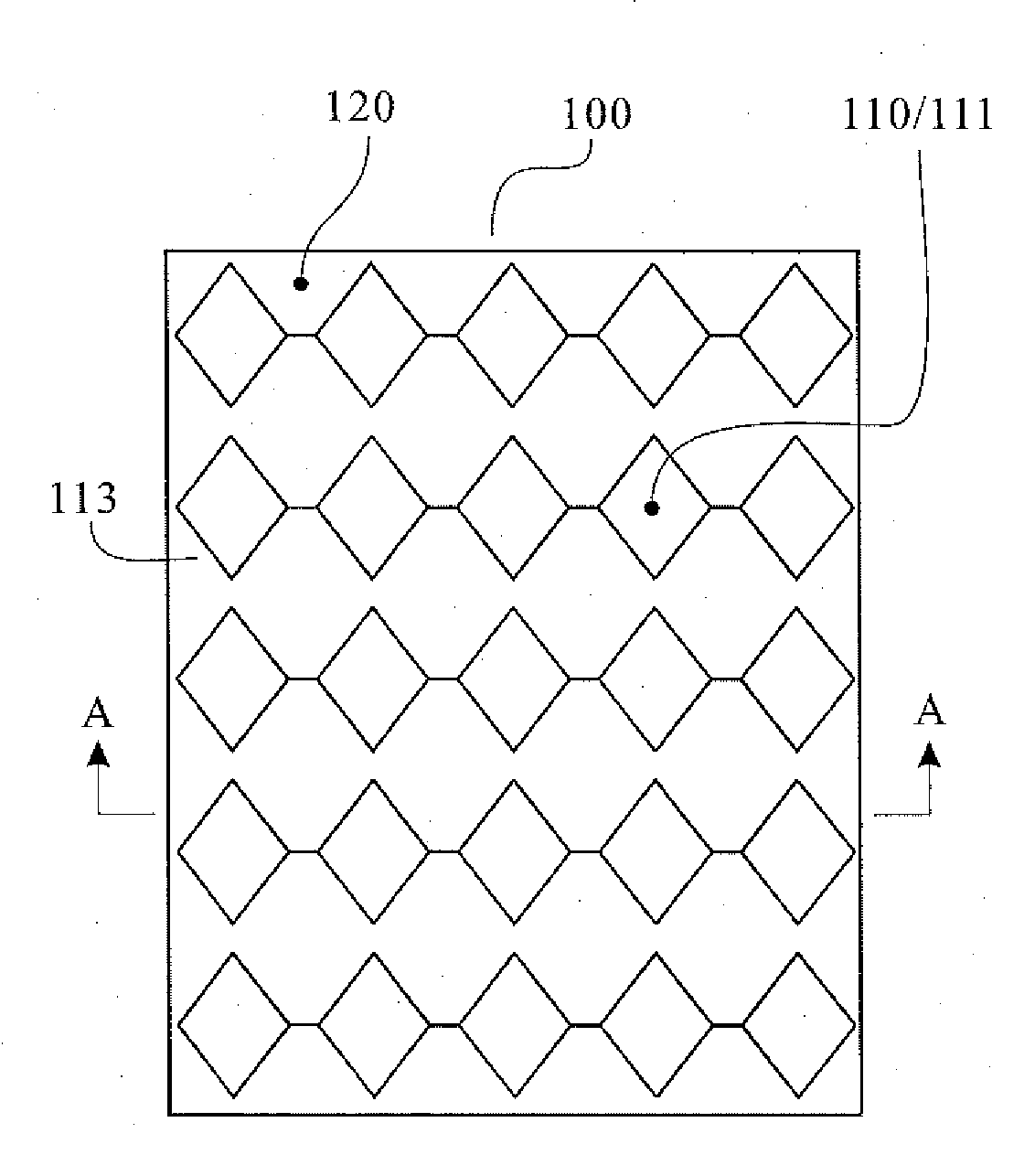
[0042]In the invention, the upper electrode film 100 is not provided with the dummy electrode plates 112, and the upper electrode plates 111 and the lower electrode plates 211 are rhombic as shown in FIG. 1. The upper electrode plates 111 are connected in series to be a plurality of upper electrode chains 113 laterally in group, wherein the connecting lines for the electrode plate centroids are parallel mutually; the lower electrode plates 211 are connected in series to be a plurality of lower electrode chains 213 longitudinally in group, wherein the connecting lines for the electrode plate centroids are parallel mutually. Any connecting line for the electrode plate centroids of the upper electrode chains 113 is perpendicular to any connecting line for the electrode plate centroids of the lower electrode chains 213. As shown in FIG. 1-3, the touch screen can not be subject to interference from the display screen 400 under the shielding effect of the shielding electrode plate 212, an...

third embodiment

[0044]In the invention, the upper electrode film 100 is provided with the dummy electrode plates 112, and the upper electrode plates 111 and the lower electrode plate 211 are rectangular as shown in FIG. 3. The upper electrode plates 111 are connected in series to be a plurality of upper electrode chains 113 longitudinally in group, wherein the connecting lines for the electrode plate centroids are parallel mutually; the lower electrode plates 211 are connected in series to be a plurality of lower electrode chains 213 laterally in group, wherein the connecting lines for the electrode plate centroids are parallel mutually. Any connecting line for the electrode plate centroids of the upper electrode chains 113 is perpendicular to any connecting line for the electrode plate centroids of the lower electrode chains 213. The dummy electrode plates 112 are over against the lower electrode plates 211, i. e. the electrode plane 110 of the upper electrode film 100 and the area over against ea...

fourth embodiment

[0045]In the invention, the upper electrode film 100 is provided with the dummy electrode plates 112, the upper electrode plates 111 are hexagonal, and the lower electrode plates 211 are rhombic as shown in FIG. 4. The upper electrode plates 111 are connected in series to be a plurality of upper electrode chains 113 longitudinally in group, wherein the connecting lines for the electrode plate centroids are parallel mutually; the lower electrode plates 211 are connected in series to be a plurality of lower electrode chains 213 laterally in group, wherein the connecting lines for the electrode plate centroids are parallel mutually. Any connecting line for the electrode plate centroids of the upper electrode chains 113 is perpendicular to any connecting line for the electrode plate centroids of the lower electrode chains 213. The dummy electrode plates 112 are over against the lower electrode plates 211, i. e. the electrode plane 110 of the upper electrode film 100 and the area over ag...


PUM


Abstract

A mutual capacitance touch screen with electrodes arranged on dual conductive material films, which comprises an upper electrode film and a lower electrode film, and the two electrode films respectively comprise an electrode plane made of transparent conductive materials and an insulated plane made of transparent insulating materials. The insulated planes of the two electrode films are fused together. Lower electrode plates are arranged on the electrode plane of the lower electrode film separately, and shielding electrode plates are arranged in the clearance between the lower electrode plates. Therefore, the lower electrode plates and the shielding electrode plates are distributed to the whole electrode plane of the lower electrode film. The touch screen of the present invention can isolate interference from the display screen in the conditions that the thickness is not increased and the shielding electrode film is not required to be arranged individually. Therefore, the manufacturing cost of the touch screen is reduced.

Description

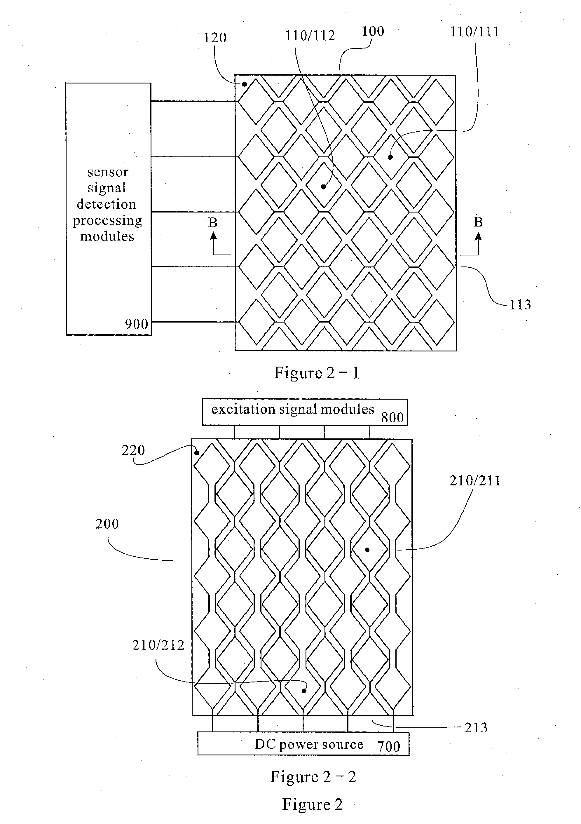
TECHNICAL FIELD[0001]The present invention relates to a data input device converting action message to required electrical signals, particularly to a capacitive touch screen with electrodes arranged on films.BACKGROUND ART[0002]The mutual capacitance touch screen in the prior art comprises driving electrodes electrically connected to peripheral excitation signal modules of the touch screen, and sensing electrodes electrically connected to peripheral sensor signal detection processing modules of the touch screen, and mutual capacitance is formed between the driving electrodes and the sensing electrodes. When the surface of the mutual capacitance touch screen is touched, the mutual capacitance value within areas using the touch point as center will be changed, thereby converting the touch action message to electrical signals. Coordinate data of the touch action center can be obtained by processing data of capacitance value changing areas, then associated data processing equipment can ...

Claims


Application Information

Patent Timeline
IPC IPC(8): G06F3/045
CPCG06F2203/04103G06F3/044G06F3/0446G06F3/0445
Inventor MO, MICHAELZHANG, JKPENG, LING
Owner FOCALTECH SYSTEMS LTD
Learn More