Riveting robot system

a robot and robot technology, applied in the field of riveting and fastening, can solve the problems of only being able to meet the requirements of pneumatic riveting tools, only being able to use automatic riveting of rivet pulling nuts, and entanglement of safety hazards, so as to improve the operating state of the robot, isolate the interference of the riveting operation, and improve the effect of riveting accuracy

Active Publication Date: 2021-09-23
MEISHAN CRRC FASTENING SYST CO LTD
View PDF0 Cites 6 Cited by
  • Summary
  • Abstract
  • Description
  • Claims
  • Application Information

AI Technical Summary

Benefits of technology

[0029]The beneficial effects of the present invention are as follows: the riveting robot system provided in the present invention can realize unmanned quick mounting of a pulling rivet at a specific riveting position, and can realize functions during operation including automatic change of the riveting tool part, automatic alignment of riveting position holes, automatic loading and binding, automatic riveting, and automatic judgment of the riveting quality, storage, and so forth. The vibration damping structure in the prevent invention effectively isolates interference of riveting operation of a robot from a vibration source, improve the riveting accuracy and improve the operating state of the robot. The vibration damping structure is simple and effective. The radial and axial damping mechanisms can absorb axial and radial impact energies during the process of rivet pulling and mounting, ensuring that the operating accuracy of the riveting robot system and service life of the riveting robot mechanism.

Problems solved by technology

Meanwhile, due to the operators' and inspectors' negligence, there may be problems such as missed riveting, missed inspection or erroneous inspection, bringing enormous hidden safety hazards.
The patent can only be used in automatic riveting of rivet pulling nuts.
The mounting tools are pneumatic riveting tools which cannot satisfy the requirements for automatic riveting of break-type pulling rivets.

Method used


Image

  • Riveting robot system
  • Riveting robot system
  • Riveting robot system

Examples


Embodiment Construction

[0040]The present invention was specifically described through embodiments which were only used for further explaining the present invention, and could not be understood as limiting the scope of protection of the present invention. Some non-substantive improvements and adjustments made by a person skilled in the art according to the contents in the present invention also fell within the scope of protection of the present invention.

[0041]The figures were combined.

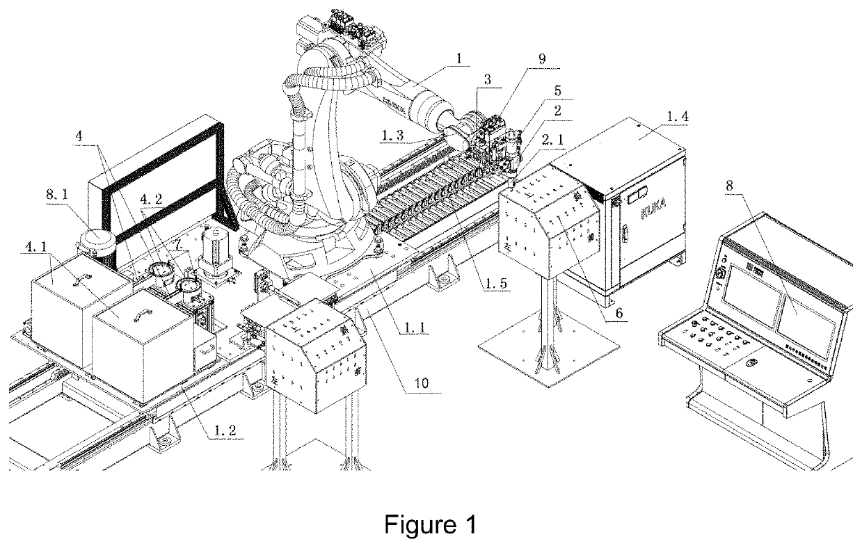
[0042]A riveting robot system comprised: a robot part 1, a riveting tool part 2, a visual position identification part 3, an automatic rivet feeding part 4, a riveter tailing material collection part 5 and a riveting quality judgment part 8. After the riveting robot system was started, the specifications of a riveting position hole 6 and a rivet 7 were arranged. The robot automatically selected the riveting tool part 2 for quick change. The automatic rivet feeding part 4 completed feeding of rivet 7. The riveting tool part 2...


PUM

PropertyMeasurementUnit
dampingaaaaaaaaaa
vibration dampingaaaaaaaaaa
axial dampingaaaaaaaaaa

Abstract

The present invention discloses a riveting robot, comprising: a robot part provided on a chassis, and detachably coupled with a riveting tool part through a hydraulically quick change disk; a visual position identification part provided on a side of the hydraulically quick change disk and secured on the sixth axis of the front end of the robot part; an automatic rivet feeding part provided on a mounting baseplate which is secured on a chassis through a two-stage vibration damping structure; a riveter tailing material collection part used for collecting tailing materials produced during riveting; a riveting quality judgment part used for collecting riveting data, and processing and generating a riveting curve to realize judgment of the riveting quality.

Description

TECHNICAL FIELD[0001]The present invention belongs to the technical field of riveting and fastening, and belongs to the technical field of designing and manufacturing smart devices for riveting and fastening in particular. The present invention especially relates to a smart device system for pulling rivet fastening and connection, and a riveting robot specifically, falling within the riveting type (B21 J).BACKGROUND ART[0002]The pulling rivet fastening and connection technology has been widely applied in industries including railways, aviation, automobiles, vessels and so forth. However, during mounting and use thereof in large batches at fixed operating positions, operators shall hold riveting tools in hand for riveting. As for the case where there is a great amount of riveting, the operators shall make great efforts. Meanwhile, due to the operators' and inspectors' negligence, there may be problems such as missed riveting, missed inspection or erroneous inspection, bringing enormo...

Claims


Application Information

Patent Timeline
Patent Type & Authority Applications(United States)
IPC IPC(8): B21J15/30B25J11/00
CPCB21J15/30B25J11/007B21J15/32B21J15/10B21J15/043B21J15/20B21J15/326F16F15/08B21J15/28B25J19/0091B25J17/0225F16F1/3732F16F1/371B21J15/022B23P19/004B65G27/08
Inventor ZHAO, XIANGYUNLIU, YUDENG, TAOLI, WEIYU, TAOGUO, LONGZHANG, SHUAILI, KUNYANG, LIN
Owner MEISHAN CRRC FASTENING SYST CO LTD
Why Eureka
Try Eureka