
Display input device and navigation device

a technology of navigation device and display input, which is applied in the direction of instruments, computing, electric digital data processing, etc., can solve the problems of difficult control operation, difficult to see icons in the surrounding area other than the button icon pushed down, and affect the ease of use of the device, etc., to achieve excellent ease of use and easy control

Inactive Publication Date: 2011-09-15
MITSUBISHI ELECTRIC CORP
View PDF12 Cites 160 Cited by
  • Summary
  • Abstract
  • Description
  • Claims
  • Application Information

AI Technical Summary

Benefits of technology

[0010]The present invention is made in order to solve the above-mentioned problems, and it is therefore an object of the present invention to provide a display input device that is easily controlled and that provides excellent ease of use which does not make the user have a feeling that something is abnormal in performing an operation.
[0012]Therefore, the display input device in accordance with the present invention is easily controlled, and provides excellent ease of use which does not make the user have a feeling that something is abnormal in performing an operation.

Problems solved by technology

However, because the size of the icon which the user is going to push down varies before he or she brings the finger close to the icon, the user has a feeling that something is abnormal in performing the operation, and this may impair the ease of use of the device contrarily.
Furthermore, according to the technology disclosed by patent reference 2, if the position of the finger is too far away from the touch panel surface when trying to control the scaling, the scaling sways due to a vibration in the Z axial direction of the finger, and therefore the control operation may become difficult.
However, a drawback to this technology is that icons in a surrounding area other than the button icon pushed down are hard to be visible.

Method used


Image

  • Display input device and navigation device
  • Display input device and navigation device
  • Display input device and navigation device

Examples


embodiment 1

[0020]

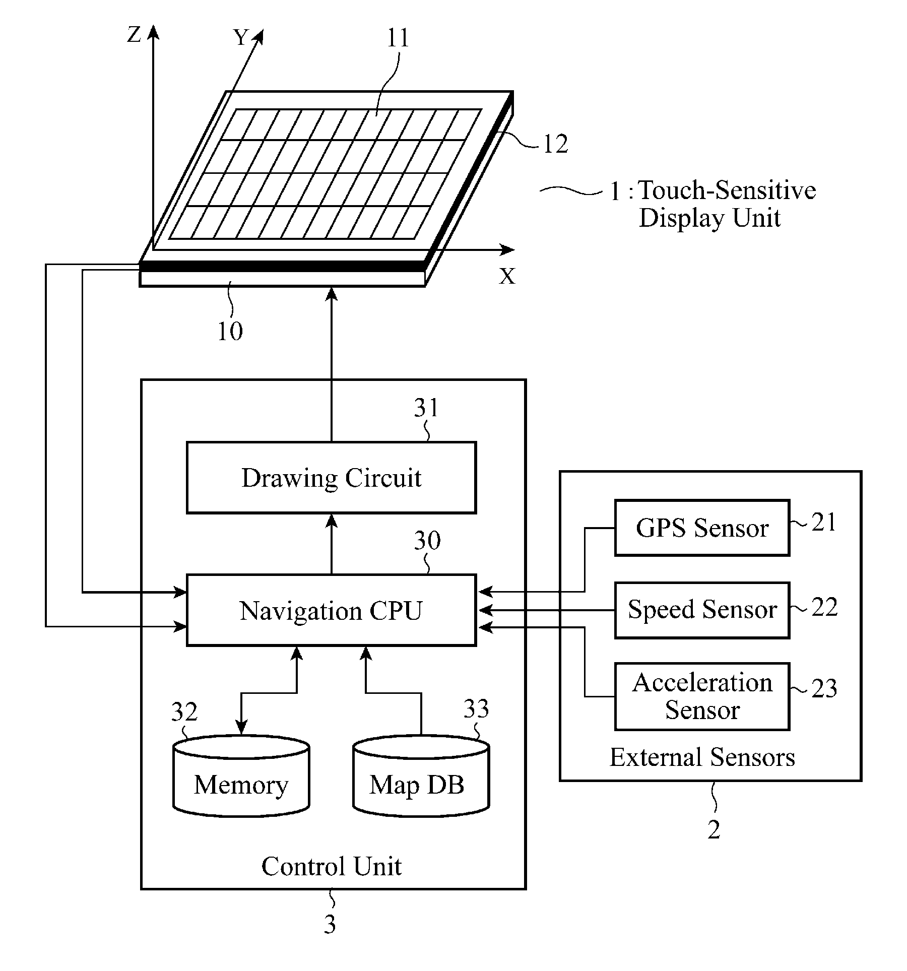
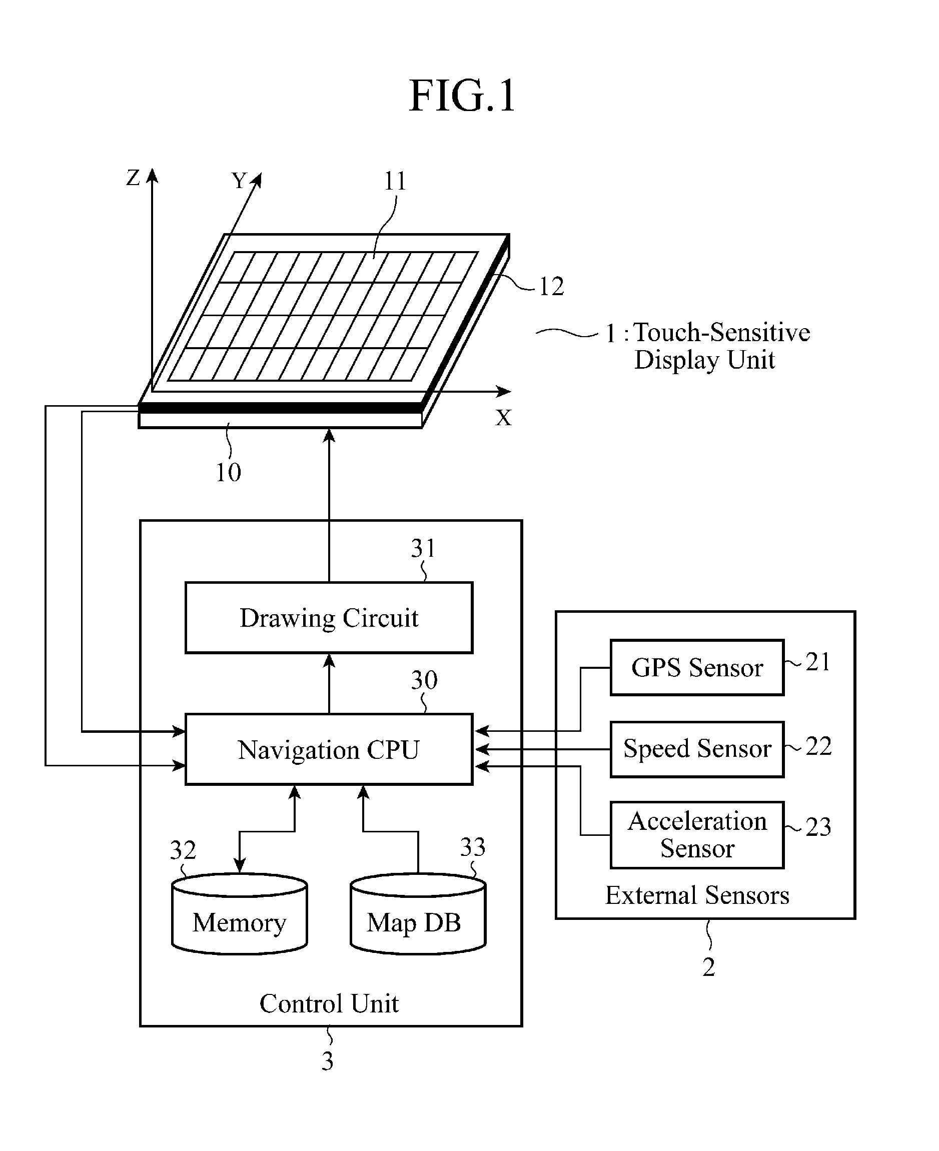
[0021]FIG. 1 is a block diagram showing the structure of a display input device in accordance with Embodiment 1 of the present invention. As shown in FIG. 1, the display input device in accordance with Embodiment 1 of the present invention is comprised of a touch-sensitive display unit (abbreviated as a touch panel from here on) 1, external sensors 2, and a control unit 3.

[0022]The touch panel 1 carries out a display of information and an input of the information. For example, the touch panel 1 is constructed in such a way that a touch sensor 11 for inputting information is laminated on an LCD panel 10 for displaying information. In this embodiment, the touch panel 1 and a plurality of proximity sensors 12 each of which carries out non-contact detection in two dimensions of a movement of an object to be detected, such as a finger or a pen, which is positioned opposite to the touch panel 1 are mounted on a peripheral portion outside the touch sensor 11 on a per-cell basis.

[0023...

embodiment 2

[0065

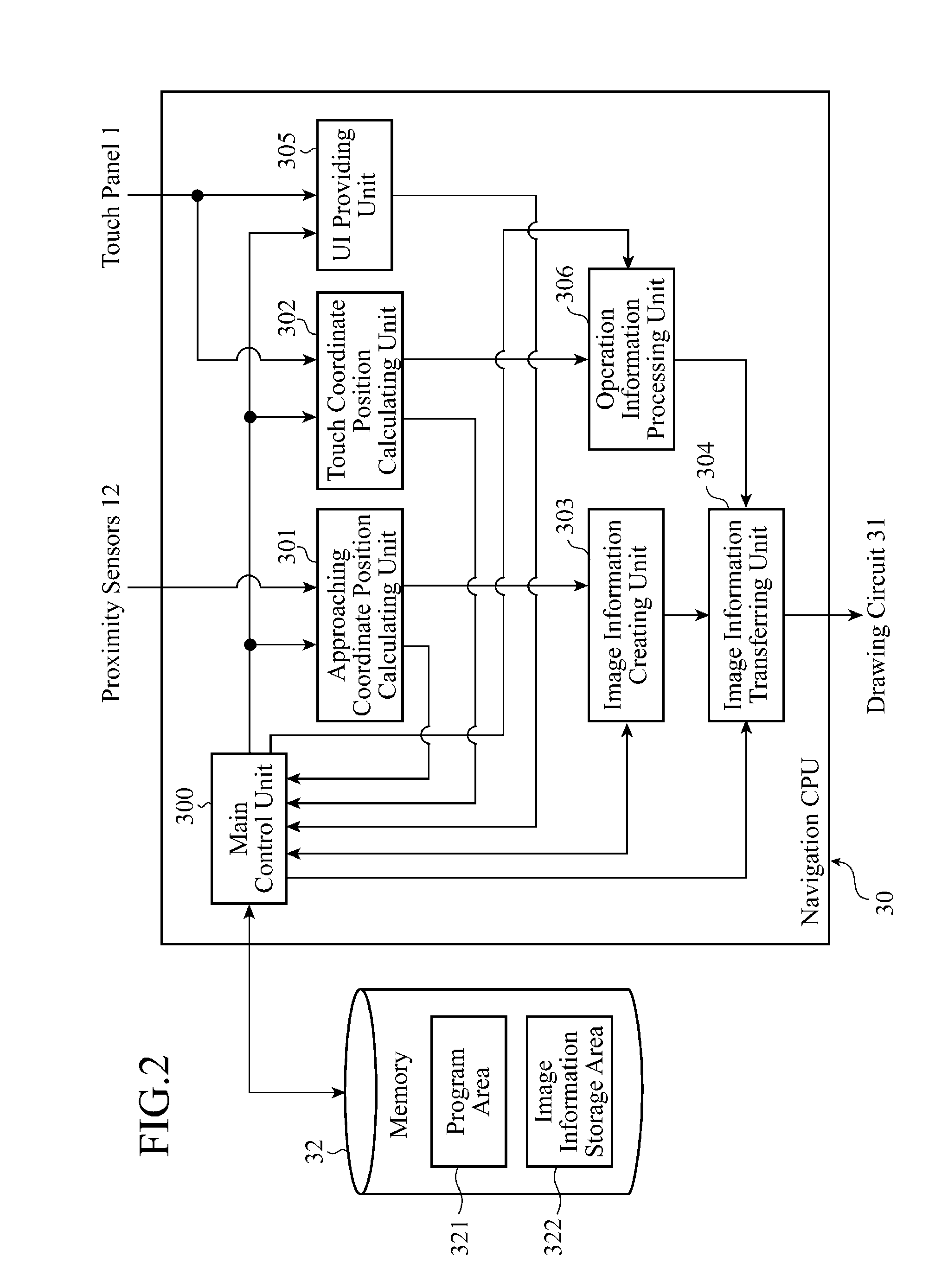
[0066]FIG. 7 is a block diagram showing a functional development of the structure of a program which a navigation CPU 30, which a display input device (a control unit 3) in accordance with Embodiment 2 of the present invention has, executes.

[0067]The display input device in accordance with Embodiment 2 of the present invention differs from that in accordance with Embodiment 1 shown in FIG. 2 in that a display attribute information creating unit 307 is added to the program structure of the navigation CPU 30 in accordance with Embodiment 1 from which the UI providing unit 305 is excluded.

[0068]In order to process external icons displayed on a touch panel 1 to display the external icons in distinction from internal icons, the display attribute information creating unit 307 creates attribution information used to carry out display decoration control of an image according to a display attribute, such as tone, color, blink, reverse, or emphasis, for each image information created by ...

embodiment 3

[0081

[0082]FIG. 10 is a flowchart showing the operation of a display input device in accordance with Embodiment 3 of the present invention. It is assumed that the display input device in accordance with Embodiment 3 which will be explained hereafter uses the same structure as the display input device shown in FIG. 1 and uses the same program structure as that shown in FIG. 2, like that in accordance with Embodiment 1.

[0083]The display input device in accordance with Embodiment 3 which will be explained hereafter is applied to a three-dimensional touch panel which can also measure the distance in a Z direction between its panel surface and a finger. More specifically, the touch panel 1 shown in FIG. 1 that can detect the position of an object in the X and Y directions is replaced by the three-dimensional touch panel that can also measure a distance in the Z direction. Because a technology of measuring a three-dimensional position is disclosed by above-mentioned patent reference 2, an...


PUM


Abstract

A display input device is comprised of a touch panel 1 for carrying out a display of an image and an input of an image, a proximity sensor 12 for detecting a movement of an object to be detected which is positioned opposite to the touch panel 1 in a non-contact manner, and a control unit 3 for, when the proximity sensor 12 detects an approach of the object to be detected to within a predetermined distance from the touch panel 1, processing an image around a display area having a fixed range on the touch panel 1 in a vicinity of the object to be detected, and displaying the image in distinction from an image in the display area having the fixed range.

Description

FIELD OF THE INVENTION[0001]The present invention relates to a display input device which is particularly suitable for use in vehicle-mounted information equipment such as a navigation system.BACKGROUND OF THE INVENTION[0002]A touch panel is an electronic part which is a combination of a display unit like a liquid crystal panel, and a coordinate position input unit like a touchpad, and is a display input device that enables a user to touch an image area, such as an icon, displayed on the liquid crystal panel, and detects information about the position of a part of the image area which has been touched by the user to enable the user to operate target equipment. Therefore, in many cases, a touch panel is incorporated into equipment, such a vehicle-mounted navigation system, which has to mainly meet the need for the user to handle the equipment by following a self-explanatory procedure.[0003]Many proposals for improving the ease of use and user-friendliness of a man-machine device incl...

Claims


Application Information

Patent Timeline
Patent Type & Authority Applications(United States)
IPC IPC(8): G09G5/00G06F3/041G06F3/048G06F3/0481G06F3/0488
CPCG06F3/0421G06F3/044G06F2203/04805G06F3/04886G06F3/0481
Inventor SHIMOTANI, MITSUOMATSUBARA, TSUTOMUSADAHIRO, TAKASHIOHTA, MASAKOOKANO, YUICHISEMPUKU, TSUYOSHI
Owner MITSUBISHI ELECTRIC CORP
Learn More