

Scanning line driving circuit
- Summary
- Abstract
- Description
- Claims
- Application Information
AI Technical Summary
Benefits of technology
Problems solved by technology
Method used
Image

Examples
first preferred embodiment
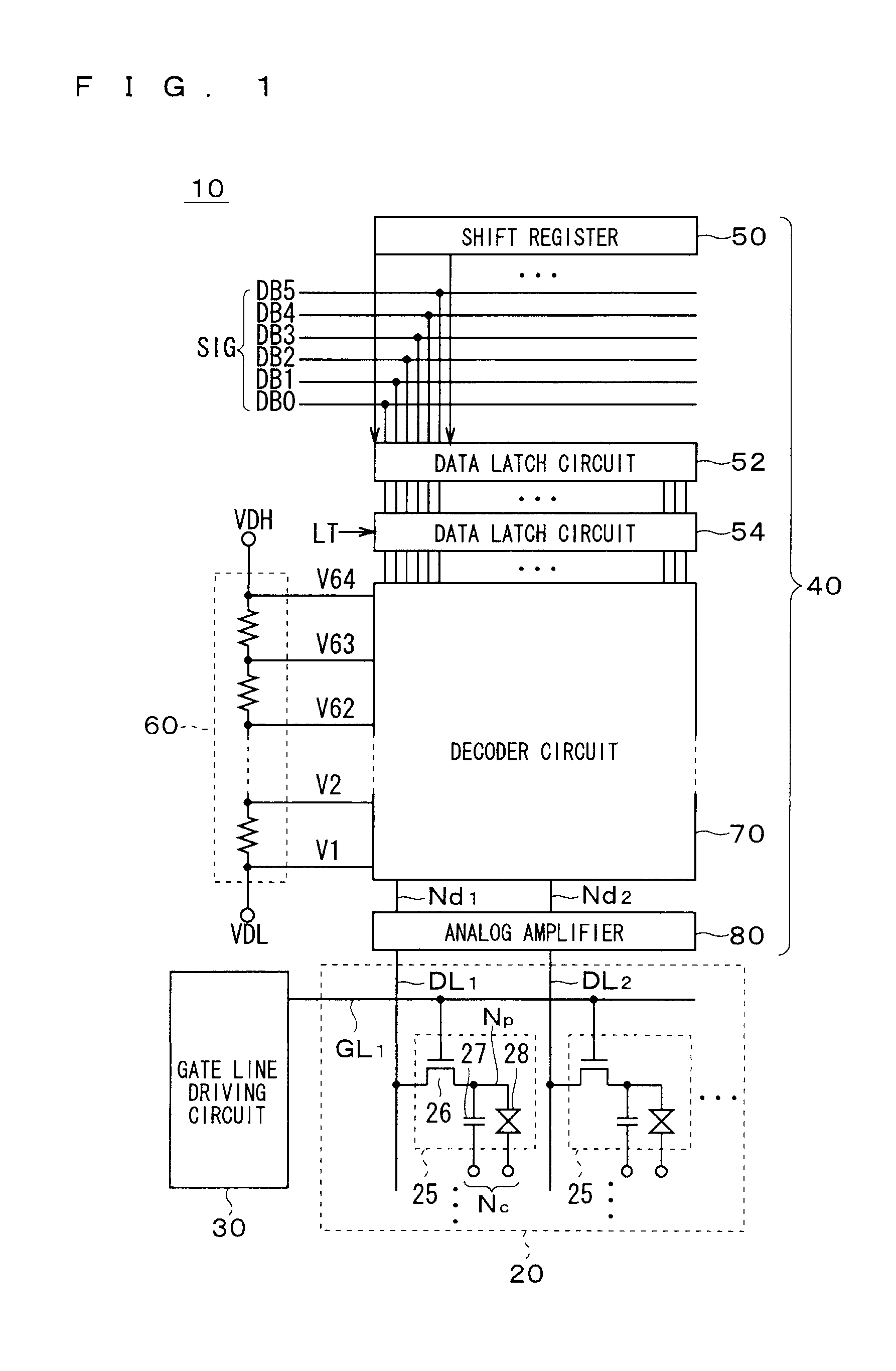
[0036]FIG. 1 is a schematic block diagram showing a configuration of a display device according to the present invention, which shows an overall configuration of a liquid crystal display device as a representative display device. Note that the application of the present invention is not limited to a liquid crystal display device, and the present invention is widely applicable to, for example, an electroluminescense (EL), organic EL, plasma display and electronic paper that is a display device converting an electric signal into light brightness, and an electro-optical device such as an imaging device (image sensor) that converts the light intensity into an electric signal.
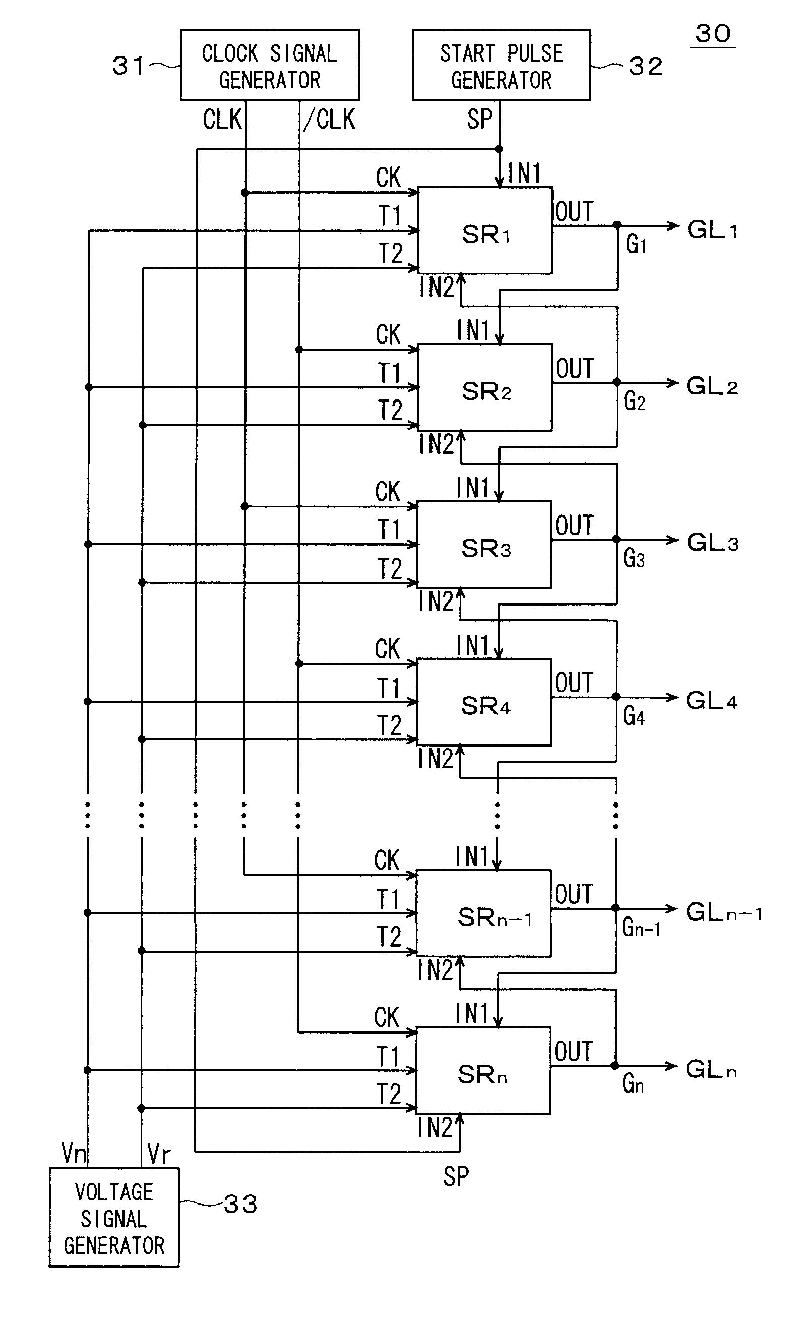
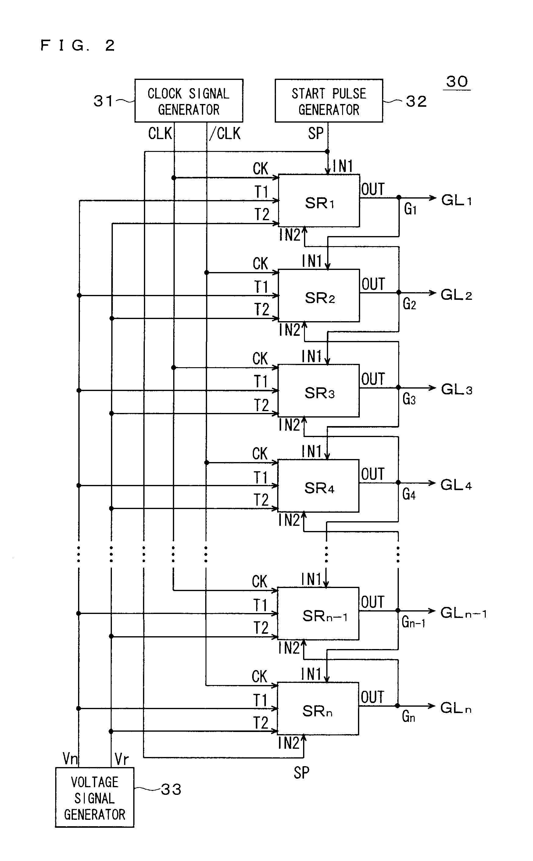
[0037]A liquid crystal display device 10 includes a liquid crystal array unit 20, a gate line driving circuit (scanning line driving circuit) 30 and a source driver 40. As will be apparent from the description below, shift registers according to this preferred embodiment are mounted in the gate line driving circuit ...
PUM
 Abstract
Description
Claims
Application Information