Mechanical rotor

a mechanical rotor and rotor body technology, applied in the direction of rotors, greenhouse gas reduction, vessel construction, etc., can solve the problems of large and cumbersome, many devices suitable for wind torque gathering are impractical or structurally unsound, and many are overly complicated

Inactive Publication Date: 2011-09-15
CARDEN MELVIN DON
View PDF10 Cites 26 Cited by
  • Summary
  • Abstract
  • Description
  • Claims
  • Application Information

AI Technical Summary

Benefits of technology

[0021]The invention is a simple unique device, similar to a water wheel designed to gather usable torque energy from the excess linear kinetic force existing at natural moving substances such as flowing rivers, s

Problems solved by technology

Many devices suitable for gathering torque from wind are impractical or structurally unsound when encountering the force of flowing water.
Many are overly complicated, using special sp

Method used


Image

  • Mechanical rotor
  • Mechanical rotor
  • Mechanical rotor

Examples


Embodiment Construction

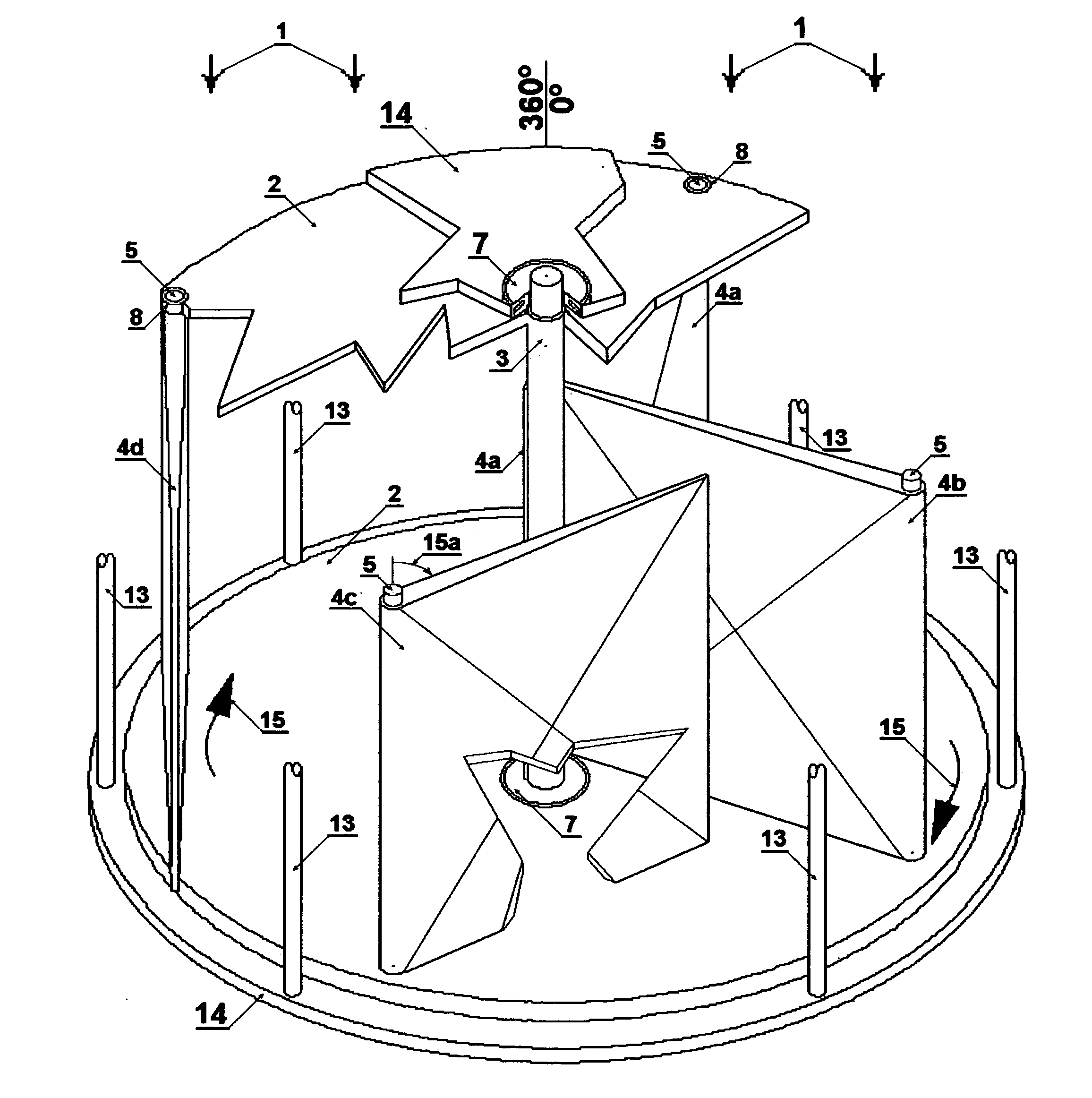
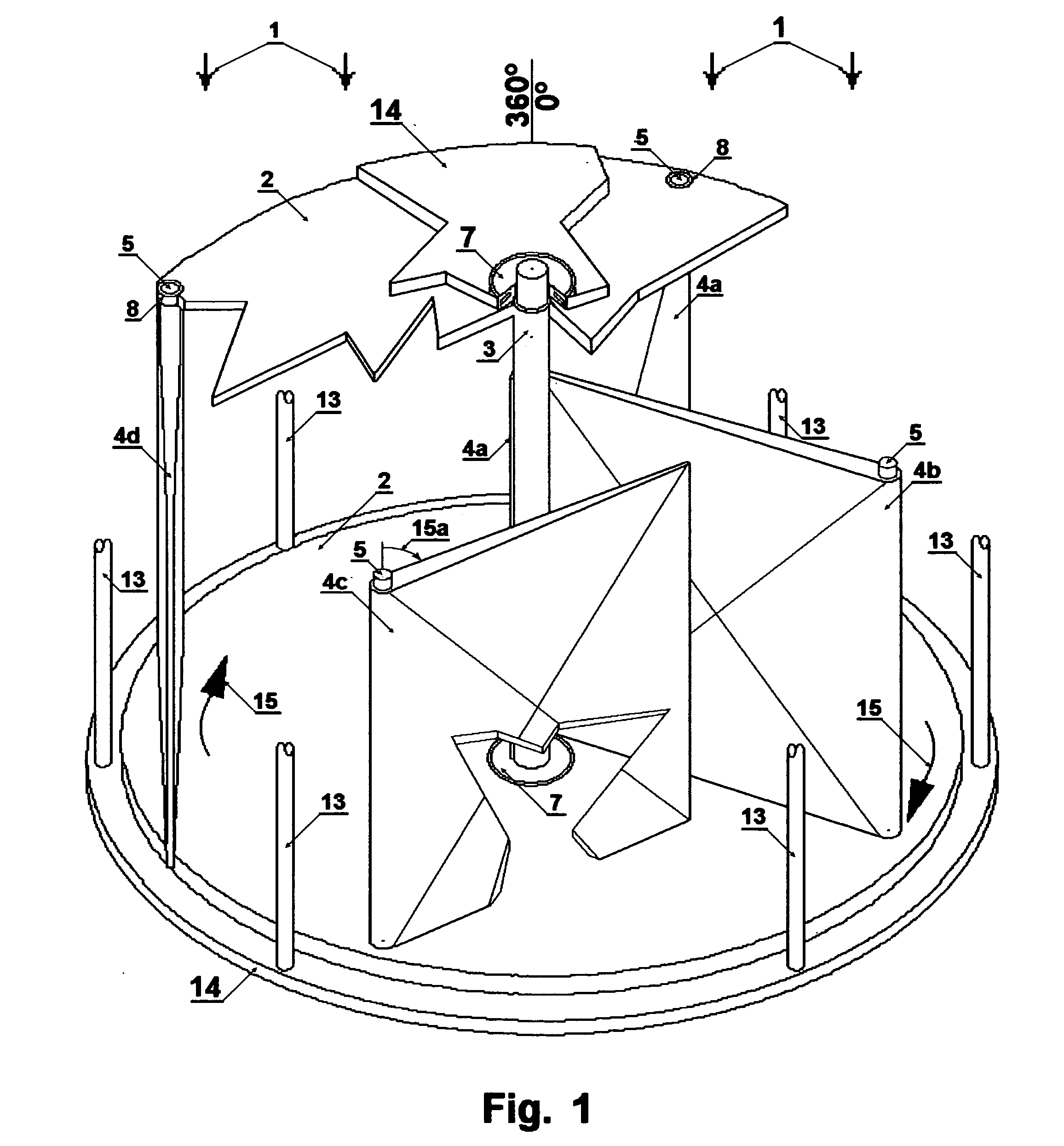
[0072]The following description illustrates the invented device as being functionally a waterwheel, rotating on a axis, harvesting torque energy from the positive drag force of flowing linear force of streams, rivers, ocean tides or wind. Adaptation of free swinging foils that self position according to the dynamic conditions to which they are subjected by the flowing linear force, creates a condition which develops a secondary method of extracting torque from flowing streams, rivers, ocean tides, or winds.

[0073]FIG. 1 displays a vertical axis arrangement of the invention showing an Isometric sketch of the essential features to the Mechanical Rotor exposed by cutaway segments within an open 360 degree cage forming a structural frame. The view is at a 22.5 degree point of rotation with 0 degree being directly into the Linear Force 1 pressure.

[0074]FIG. 1 view is applicable to a mirrored horizontal axis view or as either clockwise or counter clockwise Rotation Direction 15. As display...


PUM


Abstract

The Mechanical Rotor is a simple unique invention that salvages torque energy from excess linear kinetic energy produced by flowing rivers, streams, ocean currents, or blowing wind. The unique design of the invention salvages torque by the drag principal of Physics during part of a rotation. Rotation completion limits exposure to only a small aerodynamic surface into the pressure of the linear kinetic force.
The invention can be elongated, stacked, or clustered, and scalable, to accommodate any engineering design desired for using the salvaged torque to pump liquids, compress pneumatics, or generate electricity or any other useful purposes.

Description

CROSS-REFERENCE TO RELATED APPLICATIONS[0001]U.S. PO Application No. 61 / 189,611, Originally Filed Aug. 21, 2008STATEMENT REGARDING FEDERAL SPONSORED RESEARCH[0002]Not Applicable.REFERENCE TO SEQUENCE LISTING[0003]Not Applicable.BACKGROUND OF THE INVENTION[0004]Applicable known U.S. Patent Classification is 416 / 119; 415 / 202[0005]International Classification FO3D March 2006 (20060101); FO3B January 2002 (20060101)[0006]Searching Classifications 416, 415, 290, 244 developed the following Patent Table:[0007]U.S. Pat. No. 54,123, Water Wheel, of D. Cushman, issued Apr. 21, 1866[0008]U.S. Pat. No. 232,205, Wind Wheel J.C. Preston; Sep. 14, 1880[0009]U.S. Pat. No. 285,584, Turbine for Stream, de Laval, Sep. 25, 1883[0010]U.S. Pat. No. 1,111,350, Currant Motor, E. S. Bayley, May 12, 1913[0011]U.S. Pat. No. 2,038,467, Vertical axis wind engine, L Zanoski Apr. 21, 1936[0012]U.S. Pat. No. 3,442,492, Fluid Current Motor, E G Sullivan, May 6, 1969[0013]U.S. Pat. No. 4,325,674, Cross_flow Olle Lj...

Claims


Application Information

Patent Timeline
IPC IPC(8): F03D3/06
CPCF03B17/065F03D3/067Y02E10/74Y02B10/30Y02E10/28F05B2210/16Y02E10/30Y02E10/20
Inventor CARDEN, MELVIN DON
Owner CARDEN MELVIN DON
Why Eureka
Try Eureka