Systems and methods for fuel cell thermal management

a fuel cell and thermal management technology, applied in the direction of fuel cell control, fuel cells, electrical equipment, etc., can solve the problems of fuel cell not being able to efficiently produce electrical output, reducing the proton conductivity of fuel cells, and affecting the efficiency of fuel cell electrical outpu

Active Publication Date: 2011-09-15
DCNS SA
View PDF42 Cites 19 Cited by
  • Summary
  • Abstract
  • Description
  • Claims
  • Application Information

AI Technical Summary

Problems solved by technology

If the membrane is below this range of suitable operating temperatures, the fuel cell will not be able to efficiently produce its electrical output.
On the other hand, if the membrane is above this range of suitable temperatures, degradation of the membrane may occur.
If too little water is present, the membranes may dry out, leading to a decrease in their proton conductivity, a decrease in their effective area for proton conduction, and / or hot spots that can cause irreversible membrane damage.
If too much water is present, the fuel cell stack may flood, leading to a decrease in the availability of reactant gasses to the fuel cell electrodes and a reversible decrease in electrical output.
However, this typically results in the cathode air stream being at a different temperature than the heat exchange fluid that is delivered to the fuel cell stack.

Method used


Image

  • Systems and methods for fuel cell thermal management
  • Systems and methods for fuel cell thermal management
  • Systems and methods for fuel cell thermal management

Examples


Embodiment Construction

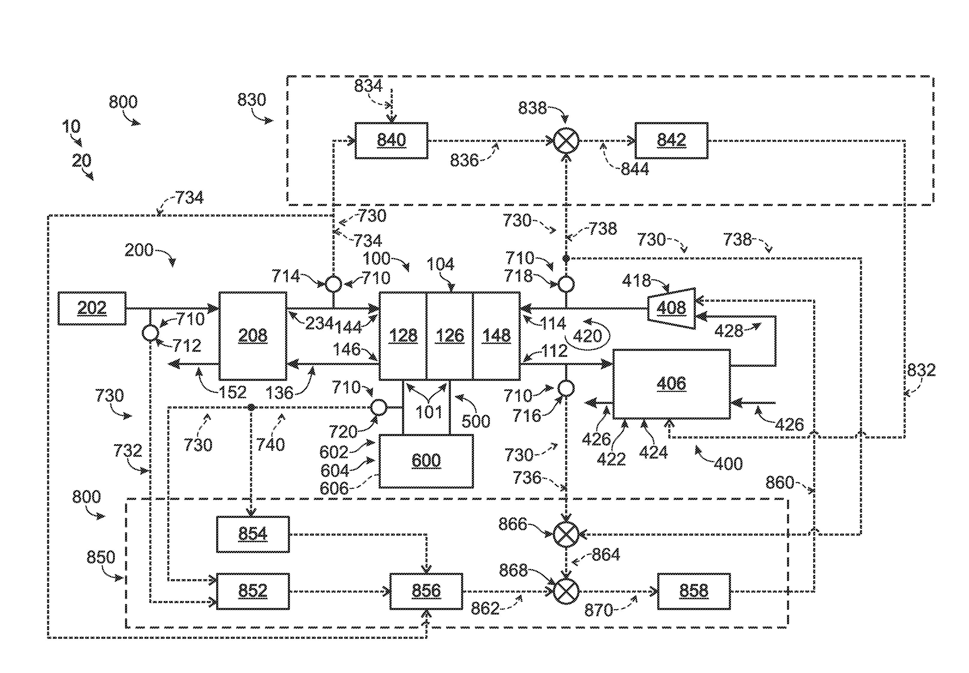
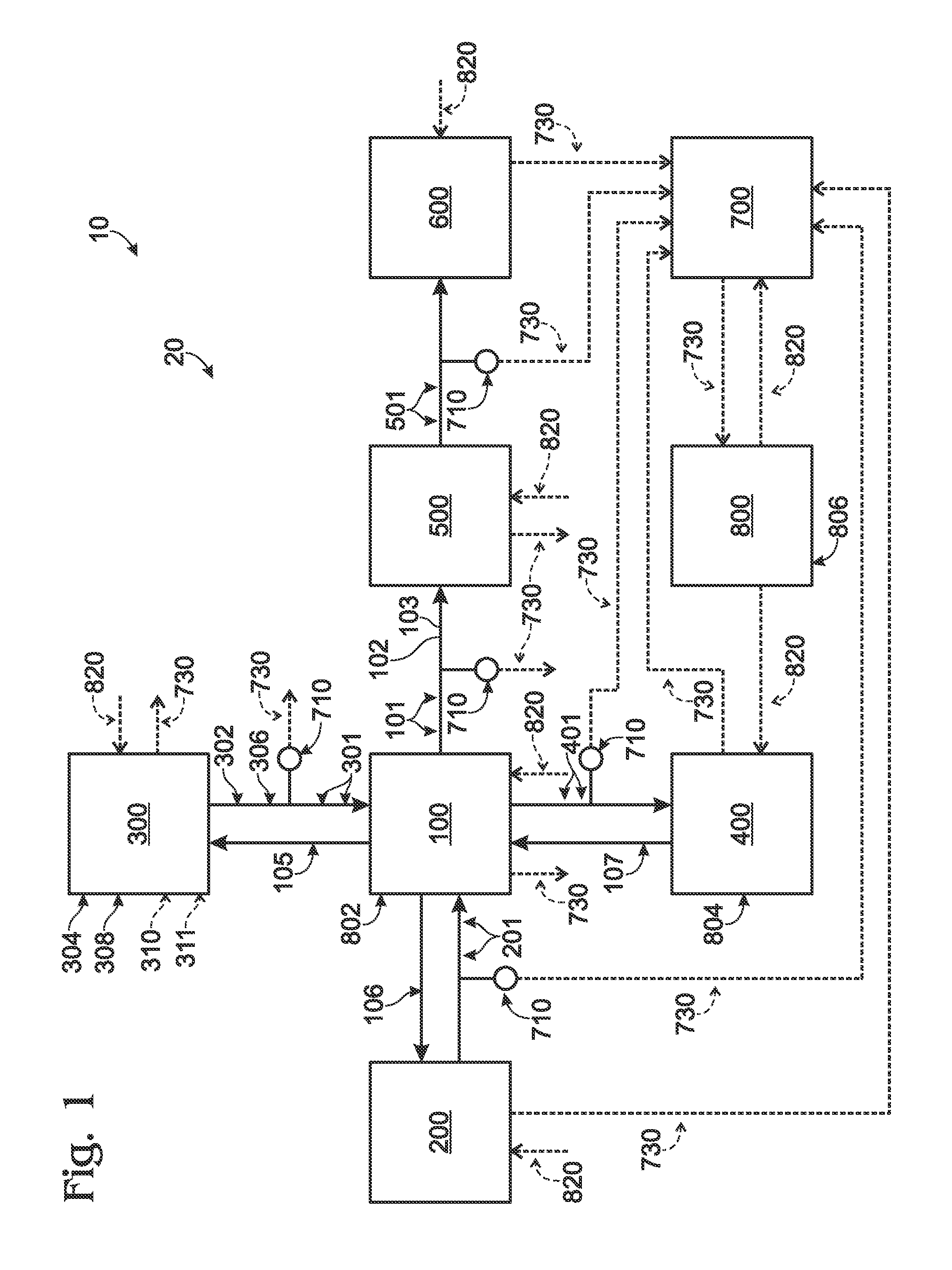
[0016]An illustrative, non-exclusive example of an energy producing and consuming assembly 10, which includes a fuel cell system 20, according to the present disclosure is schematically shown in FIG. 1. Fuel cell system 20 includes fuel cell assembly 100, oxidant supply system 200, fuel supply system 300, energy delivery system 500, energy consuming / storing assembly 600, sensor and interface system 700, and control system 800. As shown in FIG. 1, fuel cell assembly 100 receives one or more oxidant streams 201 from oxidant supply system 200 and fuel streams 301 from fuel supply system 300. Fuel cell assembly 100 is configured to utilize streams 201 and 301 in an electrochemical reaction to produce fuel cell output 101. Fuel cell output 101 may additionally or alternatively be referred to as the electrical output and / or the energy output of the fuel cell assembly, and it may further additionally or alternatively be referred to as electricity (such as is schematically indicated in FIG....


PUM

PropertyMeasurementUnit
temperatureaaaaaaaaaa
thickaaaaaaaaaa
pressuresaaaaaaaaaa

Abstract

Thermal and hydration management systems and methods for fuel cell systems, including control of electrolytic membrane hydration levels. In some embodiments, the thermal properties of the fuel cell are controlled based on a variable associated with the oxidant supply stream and / or a variable associated with the fuel cell energy output. In some embodiments, the temperature of the fuel cell is controlled based on the temperature of the oxidant supply stream. In some embodiments, the temperature range across the fuel cell stack is controlled based on the flow rate of the oxidant stream and the electrical output generated by the fuel cell stack. In some embodiments, the humidity within the fuel cell stack is controlled. In some embodiments, the liquid water content of the cathode exhaust stream is controlled.

Description

FIELD OF THE DISCLOSURE[0001]The present disclosure is related generally to thermal and hydration management systems and methods, and more specifically to systems and methods for thermal management and hydration control in fuel cell systems.BACKGROUND OF THE DISCLOSURE[0002]Fuel cell stacks are electrochemical devices that produce water and an electric potential from a fuel, such as a proton source, and an oxidant. Many conventional fuel cell stacks utilize hydrogen gas as the proton source and oxygen gas, air, or oxygen-enriched air as the oxidant. Fuel cell stacks typically include many fuel cells that are fluidly and electrically coupled together between common end plates. Each fuel cell includes an anode region and a cathode region that are separated by an electrolytic membrane. Hydrogen gas is delivered to the anode region, and oxygen gas is delivered to the cathode region. Protons from the hydrogen gas are drawn through the electrolytic membrane to the cathode region, where th...

Claims


Application Information

Patent Timeline
Patent Type & Authority Applications(United States)
IPC IPC(8): H01M8/04
CPCH01M8/04029H01M8/04335H01M8/04358H01M8/04723H01M8/04313H01M2008/1095Y02E60/50H01M8/04298H01M8/0485
Inventor LAVEN, SUDHA RANIROUVEYRE, LUC
Owner DCNS SA
Why Eureka
Try Eureka