Radio communication system, transmission system, radio terminal and radio communication method

a radio communication system and transmission system technology, applied in the field of radio communication systems, transmission systems, radio terminals and radio communication methods, can solve problems such as the inability to improve signal separation performance, and achieve the effect of improving signal separation performan

Inactive Publication Date: 2011-09-15
KYOCERA CORP
View PDF5 Cites 3 Cited by
  • Summary
  • Abstract
  • Description
  • Claims
  • Application Information

AI Technical Summary

Benefits of technology

[0018]According to the present invention, it is possible to provide a radio communication system, a transmission system, a radio terminal and a radio communication method each capable of sufficiently improving the signal separation performance by using a cooperative MIMO technique, even in a case where a propagation channel characteristic fluctuates rapidly or where a channel estimation value includes an estimation error.

Problems solved by technology

The aforementioned cooperative MIMO technique has the following problem, however.
Specifically, when a propagation channel characteristic fluctuates rapidly due to movement of the mobile terminal or when a channel estimation value acquired by channel estimation includes an estimation error, the signal separation performance cannot be improved.

Method used


Image

  • Radio communication system, transmission system, radio terminal and radio communication method
  • Radio communication system, transmission system, radio terminal and radio communication method
  • Radio communication system, transmission system, radio terminal and radio communication method

Examples


first embodiment

[0030]In a first embodiment of the present invention, descriptions will be given of (1) Schematic Configuration of Radio Communication System, (2) Detailed Configuration of Radio Communication System, (3) Example of Separation Processing, (4) Operation of Radio Communication System, and (5) Advantageous Effects.

[0031](1) Schematic Configuration of Radio Communication System

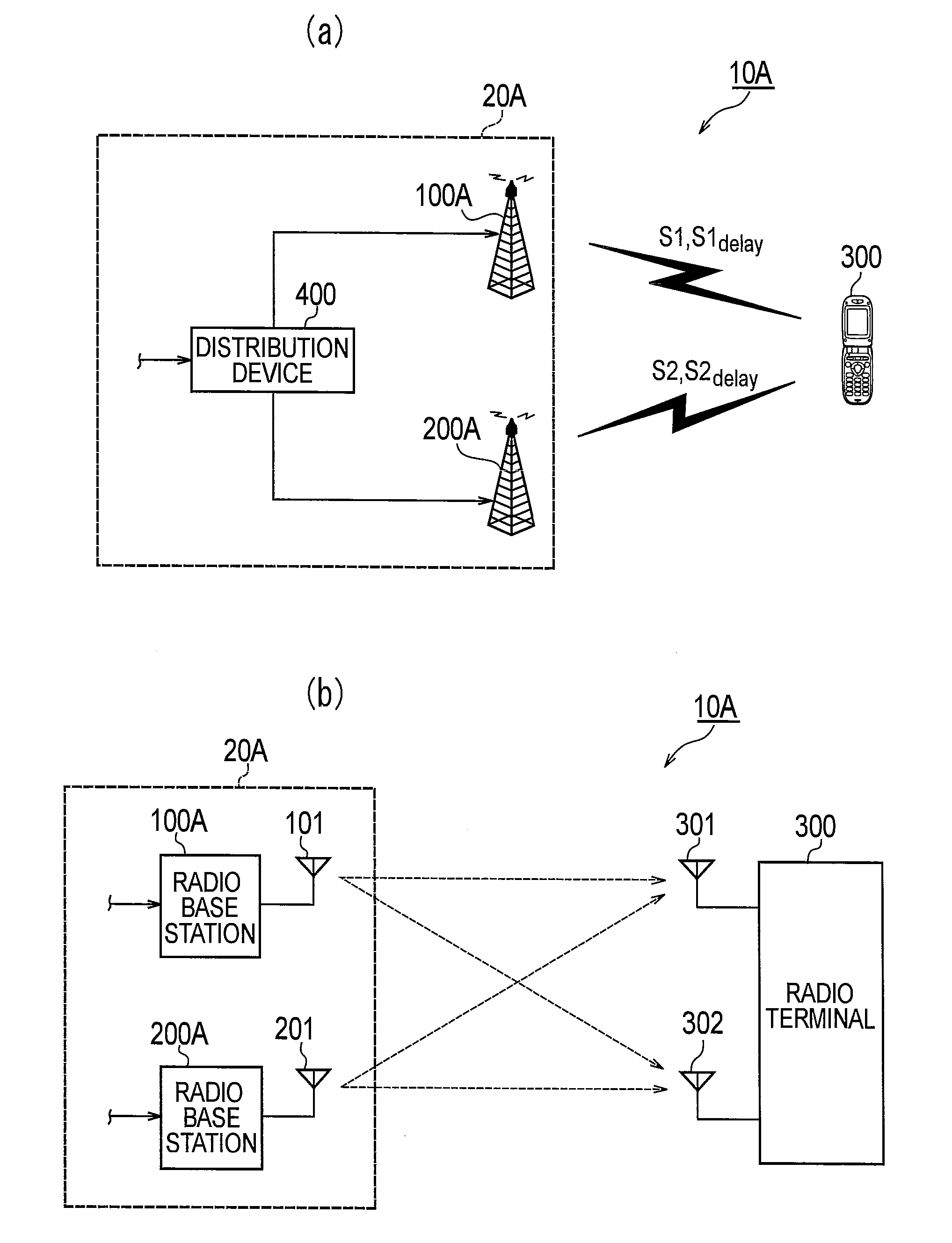
[0032]FIG. 1 is a schematic configuration diagram of a radio communication system 10A according to the first embodiment. A cooperative MIMO technique is applied to the radio communication system 10A.

[0033]As shown in FIG. 1(a), the radio communication system 10A includes a transmission system 20A and a radio terminal 300. The transmission system 20A has a radio base station 100A, a radio base station 200A and a distribution device 400.

[0034]The distribution device 400 distributes an information data sequence to be transmitted to the radio terminal 300 between the radio base stations 100A and 200A. For example, the...

second embodiment

[0105]Next, a second embodiment of the present invention will be described. The second embodiment is an embodiment in which diversity transmission is also used in addition to the configuration and operation of the first embodiment.

[0106]The configuration and operation of the radio terminal 300 is the same as those of the first embodiment. For this reason, in the second embodiment, descriptions will be given of (1) Configuration of Radio Base Station, (2) Operation of Radio Base Station, and (3) Advantageous Effects.

[0107](1) Configuration of Radio Base Station

[0108]FIG. 7 is a functional block diagram showing a configuration of a radio base station 100B (first radio communication device) and a radio base station 200B (second radio communication device) according to the second embodiment.

[0109]The radio base station 100B has two antennas 101 and 102, and the radio base station 200B has two antennas 201 and 202. Specifically, MIMO communications using four-by-two antenna configuration...


PUM


Abstract

A radio communication system (10A) has a transmission system (20A) and a radio terminal (300). The transmission system (20A) superimposes and transmits a delay stream (S1delay) and a communication stream (S1), and superimposes and transmits a delay stream (S2delay) having a different delay than the delay stream (S1delay) and a communication stream (S2). A transmission system (20A) notifies delay information (S1info) about the delay stream (S1delay) and delay information (S2info) about the delay stream (S2delay). The radio terminal (300) combines the communication stream (S1) and the delay stream (S1delay) in accordance with the notified delay information (S1info), and combines the communication stream (S2) and the delay stream (S2delay) in accordance with the notified delay information (S2info).

Description

TECHNICAL FIELD[0001]The present invention relates to a radio communication system, a transmission system, a radio terminal and a radio communication method used for multiple-input multiple-output type communications.BACKGROUND ART[0002]In recent years, various techniques for efficiently using a limited frequency band have been implemented in a radio communication system. As an example of the techniques, a multiple-input multiple-output (MIMO) technique has been known. With this technique, multiple signal sequences using the same frequency band are simultaneously transmitted via multiple transmission antennas, and the multiple signal sequences are received via multiple reception antennas and then separated from one another.[0003]In a radio communication system using the MIMO technique, the reception side receives the multiple signal sequences in an interference state, and thereafter separates the signal sequences from one another on the basis of differences among propagation channel...

Claims


Application Information

Patent Timeline
Patent Type & Authority Applications(United States)
IPC IPC(8): H04W4/00
CPCH04B7/0671H04B7/0413H04L1/02
Inventor YAMAZAKI, CHIHARU
Owner KYOCERA CORP
Why Eureka
Try Eureka