Radio communication base station device and transmission power control method

a radio communication and base station technology, applied in the direction of receiving monitoring, frequency-division multiplex, instruments, etc., can solve the problems of reducing throughput, increasing and limiting the access to an hnb, so as to reduce the transmission rate of femto user equipment, prevent the increase of signaling and reduce the transmission rate of uplink radio channel interference.

Active Publication Date: 2011-09-15
PANASONIC INTELLECTUAL PROPERTY CORP OF AMERICA
View PDF2 Cites 62 Cited by
  • Summary
  • Abstract
  • Description
  • Claims
  • Application Information

AI Technical Summary

Benefits of technology

[0023]According to the present invention, it is possible to prevent increase in signaling and decrease of the transmission rate of femto user equipment, and to reduce uplink radio channel interference from femto user equipment to a macro base station.

Problems solved by technology

In addition, it is also expected that access to an HNB is limited only to a registered user (a closed subscriber group, CSG).
Such an operation, however, raises a problem of increased uplink radio channel interference between a macrocell and a femtocell.
That is to say, there is a possibility that a tradeoff occurs in which, when throughput increases in one cell, the other cell suffers increased radio interference and decreased throughput.
In particular, when the distance between an HUE and an HNB is long and the distance between the HUE and an MNB is short, the amount of interference from the HUE to the MNB increases.
Here, when HUE transmission power reaches the maximum value, the required power that is suitable for the E-DCH transmission rate cannot be secured.

Method used


Image

  • Radio communication base station device and transmission power control method
  • Radio communication base station device and transmission power control method
  • Radio communication base station device and transmission power control method

Examples


embodiment 1

[0043]FIG. 4 is a block diagram showing the configuration of a femtocell base station according to Embodiment 1 of the present invention. In FIG. 4, receiving section 102 receives a signal transmitted from an MNB macrocell signal) and a signal transmitted from an HUE (an HUE signal) via antenna 101, outputs the macrocell signal to measurement section 103, and outputs the HUE signal to path loss estimation section 104 and scheduler 107.

[0044]Measurement section 103 measures the reception level of the macrocell signal output from receiving section 102, such as a downlink common pilot channel (CPICH), and outputs the measurement result to determination section 105. When a plurality of macrocell signals are measured, measurement section 103 outputs the maximum reception level to determination section 105. Measurement section 103 may measure only signals of a macrocell that uses the same frequency band as for a femtocell uplink radio channel, because the amount of interference to a macro...

embodiment 2

[0063]A case will be described with Embodiment 2 where, in addition to the function of interference control described in Embodiment 1, a function of changing the second threshold value depending on the macrocell signal reception power level at an HNB is provided. The configuration of a femtocell base station apparatus according to Embodiment 2 will be explained using FIG. 4 because the configuration is the same as the configuration of Embodiment 1 shown in FIG. 4.

[0064]FIG. 9 is a flowchart showing the steps of interference control according to Embodiment 2 of the present invention. Parts in FIG. 9 that are the same as in FIG. 6 will be assigned the same reference numerals as in FIG. 6 and overlapping explanations will be omitted. In FIG. 9, determination section 105 adjusts the second threshold value based on the maximum value of the macrocell signal reception power level (ST 401).

[0065]Here, when a femtocell is located farther from the center part of a macrocell, the amount of int...

embodiment 3

[0070]A case will be described with Embodiment 3 where, in addition to the function of interference control described in Embodiment 1, a function of setting a plurality of threshold values that is used for comparison with path loss between an HNB and an HUE, and a function of changing the range of lowering the maximum possible value of the target control value of total reception power depending on path loss are provided. The configuration of the femto base station apparatus according to Embodiment 3 will be explained using FIG. 4 because the configuration is the same as the configuration of Embodiment 1 shown in FIG. 4.

[0071]FIG. 13 is a flowchart showing the steps of interference control according to Embodiment 3 of the present invention. Parts in FIG. 13 that are the same as in FIG. 6 will be assigned the same reference numerals as in FIG. 6 and overlapping explanations will be omitted. In FIG. 13, determination section 105 uses a third threshold value in addition to the second th...


PUM


Abstract

Provided are a base station device and a transmission power control method that reduce interference with an uplink radio channel from a femto-connected terminal to a macrocell base station while avoiding an increase in signaling. A measurement unit (103) measures the macrocell signal reception level, and a propagation loss estimating unit (104) estimates propagation loss between a HUE and a HNB based on the HUE signal reception power, for example. A judgment unit (105) performs a first comparison of the macrocell signal reception level with a first threshold value and a second comparison of the propagation loss with a second threshold value, and an adjustment unit (106) generates a command to reduce the maximum value that is possible for the target control value for the HNB total reception power when the macrocell signal reception level is at least the first threshold value and the propagation loss is at least the second threshold value. A scheduler (107) determined a transmission rate allocated to the HUE based on the HUE signal and the maximum value that is possible for the target control value for the HNB total reception power.

Description

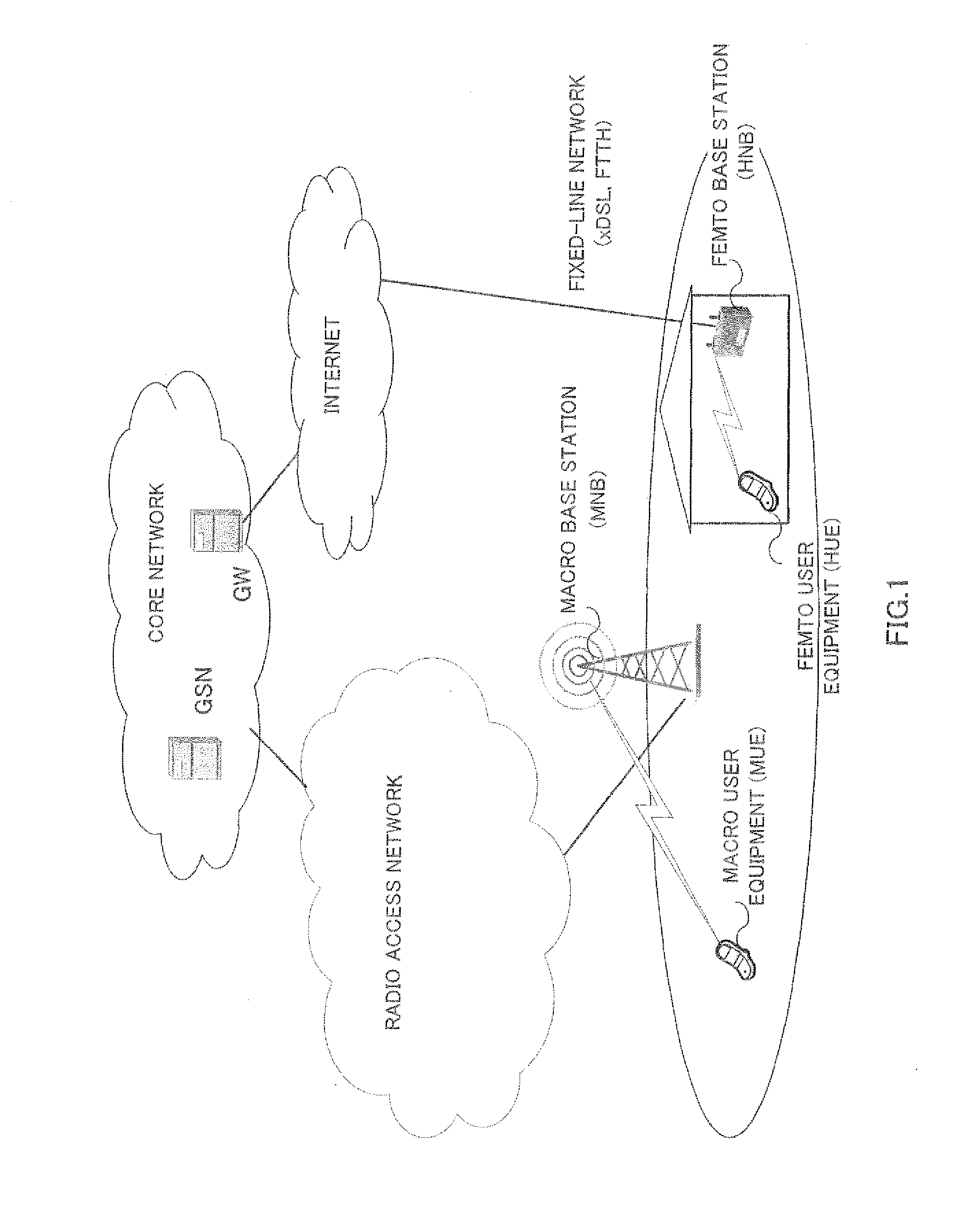
TECHNICAL FIELD[0001]The present invention relates to a radio communication base station apparatus and a transmission power control method for controlling transmission power in an uplink radio channel.BACKGROUND ART[0002]In buildings for households and offices, installation of a radio communication base station apparatus (a femto base station or a home node-B, also referred to as “HNB”) that covers a small cell or a femtocell having a cell radius of several tens of meters is considered. FIG. 1 shows the configuration of a radio system including an HNB. A mobile terminal located in the buildings in which an HNB is installed transmits data to and receives data from the HNB via a radio channel. The HNB uses a fixed-line network such as an optical fiber as a backbone to connect with a core network via a concentrator (GW).[0003]When HNBs become prevalent, it is expected that a femtocell and a macrocell share the same frequency band in urban areas and are operated in the hierarchical cell...

Claims


Application Information

Patent Timeline
Patent Type & Authority Applications(United States)
IPC IPC(8): H04W24/00H04W52/24H04B1/707
CPCH04B1/7097H04B2201/70702H04J11/0056H04W16/16H04B17/21H04W52/242H04W52/244H04W52/30H04W52/146
Inventor EBIKO, KEISUKE
Owner PANASONIC INTELLECTUAL PROPERTY CORP OF AMERICA
Why Eureka
Try Eureka