Pet/mri device, pet device, and image reconstruction system

a technology of image reconstruction and pet devices, applied in the field of pet/mri devices and pet devices, can solve the problems of longer pet measurement time and insufficient sensitivity of pet devices, and achieve the effect of short time and higher sensitivity

Inactive Publication Date: 2011-09-15
NAT INST OF RADIOLOGICAL SCI
View PDF10 Cites 27 Cited by
  • Summary
  • Abstract
  • Description
  • Claims
  • Application Information

AI Technical Summary

Benefits of technology

[0043]According to the present invention, it is possible to bring the PET detector close to the patient and / or make the effective measurement field of view of the PET detector wider than that of the MRI device, so that a PET image and an MRI image are obtained almost simultaneously in a short time.
[0044]The PET detector can be attached to the bed of the measurement object so that the PET detector comes closer to the measurement object for even higher sensitivity.

Problems solved by technology

The axial field of view of the PET device as wide as the effective axial field of view of the MRI device (30 to 40 cm or so), which is determined by the stable area of the static magnetic field, has had the problem of insufficient sensitivity of the PET device, requiring a PET measurement time longer than the MRI measurement time (typically several minutes).

Method used


Image

  • Pet/mri device, pet device, and image reconstruction system
  • Pet/mri device, pet device, and image reconstruction system
  • Pet/mri device, pet device, and image reconstruction system

Examples


first embodiment

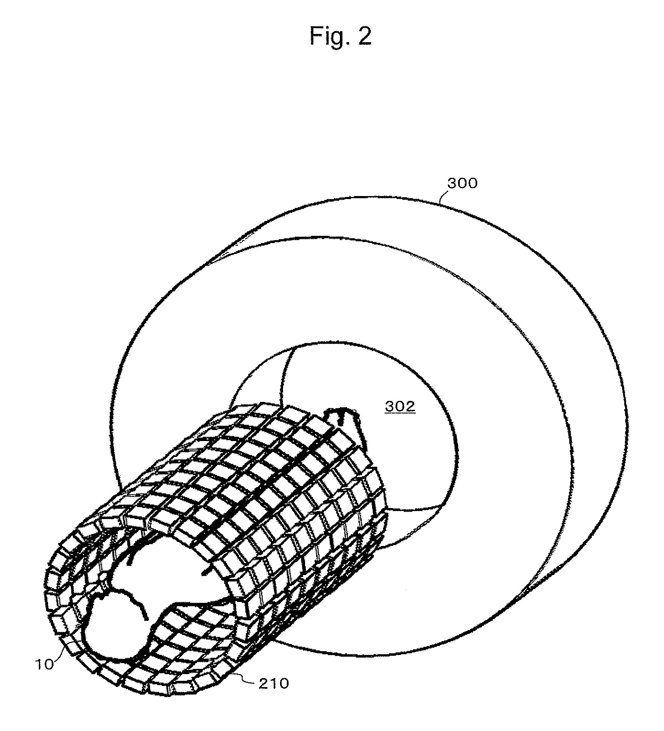
[0092]As shown in FIG. 2 (a perspective view for overview), FIG. 3A (a front view), and FIG. 3B (a sectional view seen from a side), the present invention includes an MRI device 300 and a PET detector 210. The MRI device 300 has a measurement port (here, a patient port) 302. The PET detector 210 has an outer diameter smaller than the inner diameter of the patient port 302, and can move through the patient port 302 with a measurement object (here, a patient) 10. The PET detector 210 has an effective measurement field of view (referred to as a PET field of view) P wider than the effective measurement field of view (referred to as MRI field of view) M of the MRI device 300, thereby allowing MRI measurement during PET measurement. In the diagrams, 24 denotes a cushion for protecting the patient 10, and 304 denotes an RF coil for the MRI device 300. The RF coil 304 may be integrated with the cushion 24 at the back side of the patient.

[0093]The MRI field of view M is determined by the are...

sixth embodiment

[0120]As in a sixth embodiment shown in FIG. 13 (a perspective view) and FIG. 14 (a sectional view seen from a side), the technology of the open PET device may be used to form an open area in the head PET device 212 in the vicinity of the field of view so as to alleviate the sense of confinement on the head.

seventh embodiment

[0121]As in a seventh embodiment shown in FIG. 15, the body PET detector 214 may be made of noncircular (in the diagram, elliptical) rings so that the PET detector comes closer to the patient's body.

[0122]FIGS. 16A to 16C show the configuration of essential parts where the detector rings can be changed in size according to the body type of the patient 10. FIG. 16A shows an example where normal-sized detector rings 214a are used.

[0123]FIG. 16B shows an example where large-diametered detector rings 214b are used for the abdomen. FIG. 16C shows an example where the large-diametered detector rings 214b are used not only for the abdomen but for the entire body.

[0124]FIGS. 17A to 17C show the cross sections of FIGS. 16A to 16C. FIG. 17A shows a PET detector layout for slender type, FIG. 17B shows a PET detector layout for stout type, and FIG. 17C shows a PET detector layout for the head. In the PET detector layout for stout type of FIG. 17B, the arched half portion of the detector on the ...


PUM


Abstract

A PET/MRI device includes an MRI device that has a measurement port, a PET detector that can be inserted into the measurement port, and a mechanism that can slide the PET detector into and out of the MRI measurement port. Thereby, the PET/MRI device allows MRI measurement during PET measurement.

Description

BACKGROUND OF THE INVENTION[0001]1. Field of the Invention[0002]The present invention relates to a PET / MRI device and a PET device, and more particularly to a PET / MRI device that can obtain a PET image and an MRI image almost simultaneously in a short time, and a PET device whose PET detector can be brought close to a measurement object for improved sensitivity.[0003]2. Description of the Related Art[0004]PET / CT devices such as shown in FIGS. 1A and 1B have been in widespread use, in which a CT device 100 and a PET device 200 are combined to provide a functional image of the PET device 200 superposed on a morphological image of the CT device 100 for diagnosis. In the diagrams, 10 denotes a patient or subject (hereinafter, referred to generically as a patient) to be measured (tested); 20 denotes a bed on which the patient 10 is put (lies); 22 denotes a device for moving the bed 20 in a horizontal direction; 102 denotes an X-ray tube which is the X-ray source of the CT device 100; 104...

Claims


Application Information

Patent Timeline
Patent Type & Authority Applications(United States)
IPC IPC(8): A61B5/055
CPCG01R33/56375G01R33/481G01T1/243G01R33/307G01T1/1603
Inventor YAMAYA, TAIGAOBATA, TAKAYUKI
Owner NAT INST OF RADIOLOGICAL SCI
Why Eureka
Try Eureka