Sphygmomanometer cuff and sphygmomanometer provided with the same

a sphygmomanometer and sphygmomanometer technology, applied in the field of sphygmomanometer cuff and sphygmomanometer provided with the same, can solve the problems of increased manufacturing cost, increased device size, and inability to reliably wind the cuff around the measurement site, etc., and achieves the effect of convenient attachmen

Inactive Publication Date: 2011-09-15
OMRON HEALTHCARE CO LTD
View PDF4 Cites 3 Cited by
  • Summary
  • Abstract
  • Description
  • Claims
  • Application Information

AI Technical Summary

Benefits of technology

[0011]Therefore, in view of solving the above problems, preferred embodiments of the present invention provide a sphygmomanometer cuff capable of being easily attached to the upper arm serving as the measurement site having a wide difference in size and repeating reliable winding around the upper arm in every measurement, and a sphygmomanometer provided with such a cuff.
[0025]According to a preferred embodiment of the present invention, the sphygmomanometer cuff capable of being easily attached to the upper arm serving as the measurement site having a wide difference in size and repeating reliable winding around the upper arm in every measurement and the sphygmomanometer can be obtained. Therefore, by measuring the blood pressure value by using the sphygmomanometer cuff and the sphygmomanometer including such a cuff, the blood pressure value can be precisely and stably measured and the measurement can be performed irrespective of size of the upper arm.

Problems solved by technology

On the other hand, in the sphygmomanometer in which the cuff and the main body are integrated, there are problems including a problem that the device is necessarily increased in size, a problem that the device configuration is complicated so as to increase manufacturing cost, and a problem that since measurable size of the measurement site is limited by the device configuration, a plurality of devices having different sizes of the hollow opening portions are required to be prepared in order to be widely fit for a variety of people in consideration of the size of the measurement site.
Thus, reliable winding of the cuff around the measurement site is not always repeated in every measurement.
However, even in the cuff accommodating the curler, there is a problem that a winding task thereof is troublesome in comparison to the above sphygmomanometer in which the cuff and the main body are integrated.
This pushing and extending task causes problems.
The conventional sphygmomanometer cuff has the problem that the measurable size of the upper arm serving as the measurement site is limited, and improvement is also required in this regard.

Method used


Image

  • Sphygmomanometer cuff and sphygmomanometer provided with the same
  • Sphygmomanometer cuff and sphygmomanometer provided with the same
  • Sphygmomanometer cuff and sphygmomanometer provided with the same

Examples


first preferred embodiment

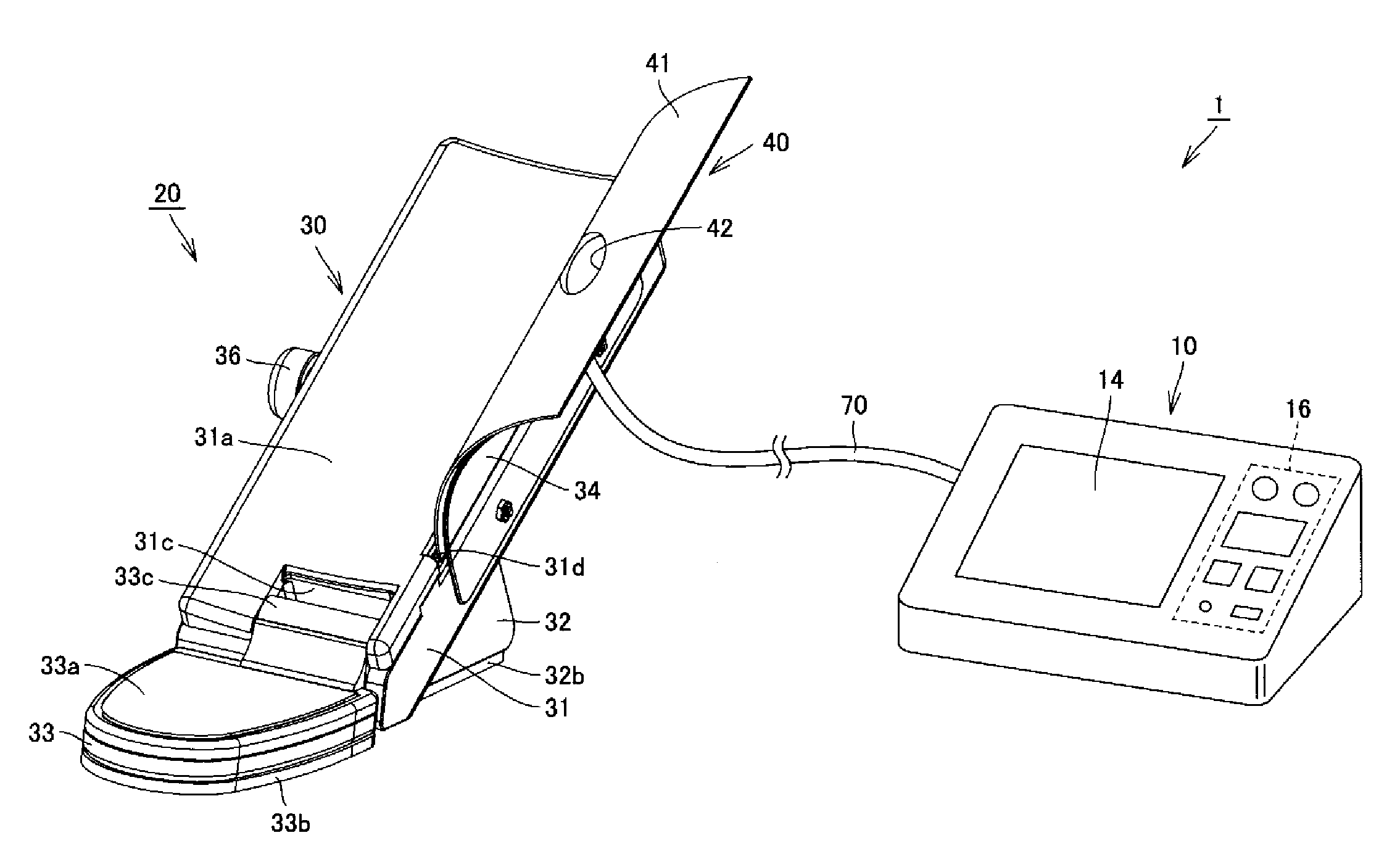
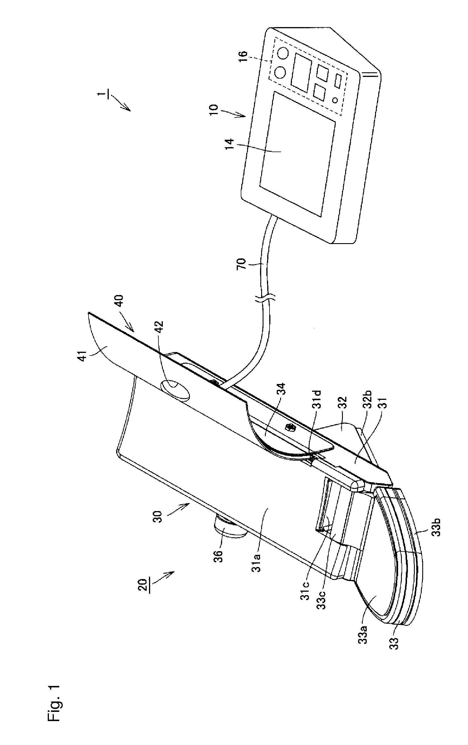
[0042]FIG. 1 is a view showing an outer appearance structure of the sphygmomanometer according to a preferred embodiment of the present invention. Firstly, with reference to FIG. 1, the outer appearance structure of the sphygmomanometer in the present preferred embodiment will be described.

[0043]As shown in FIG. 1, the sphygmomanometer 1 in the present preferred embodiment is provided mainly with a main body 10, a cuff 20, and an air tube 70. The main body 10 is mounted on a surface of a table or the like to be used during measurement, and a display unit 14 and an operation unit 16 are provided on an upper surface thereof. The cuff 20 is attached to the upper arm to be used during measurement while being mounted on the surface of a table or the like, and including an upper arm support stand 30 and an arm band 40. The air tube 70 is a member arranged to couple the main body 10 and the cuff 20 which are separated and formed by a flexible tube.

[0044]The upper arm support stand 30 of th...


PUM


Abstract

A sphygmomanometer cuff is provided with an upper arm support stand arranged to support an upper arm, and an arm band arranged to be wound around the upper arm. The upper arm support stand includes an upper arm support surface arranged to support the upper arm while the upper arm is placed thereon, a winding mechanism arranged to pull one end of the arm band in the winding direction so as to wind a portion of the arm band close to the one end, and a hook arranged to engage a portion of the arm band close to another end pulled out from the winding mechanism against a pulling force applied by the winding mechanism. The upper arm supported on the upper arm support stand is tightened by the upper arm support surface and the portion of the arm band pulled out from the winding mechanism in a state where the portion of the arm band close to the other end is engaged with the hook. With such a configuration, the sphygmomanometer cuff is capable of being easily attached to the upper arm serving as a measurement site having a difference in size as well as repeating reliable winding around the upper arm in every measurement.

Description

BACKGROUND OF THE INVENTION[0001]1. Field of the Invention[0002]The present invention relates to a sphygmomanometer cuff that can be attached to an upper arm to be used for measuring a blood pressure value (hereinafter, also simply referred to as a cuff) and a sphygmomanometer including such a cuff.[0003]2. Description of the Related Art[0004]In general, when measuring a blood pressure value, a cuff accommodating a fluid bag for compressing an artery positioned inside a living body is wound around a body surface of the living body, the wound fluid bag is expanded and contracted so as to detect an arterial blood pressure pulse wave generated in the artery, and the blood pressure value is measured based on the detected pulse wave. The cuff is a band-shaped structure having an inner cavity capable of being wound around part of the living body, which is utilized for measuring the blood pressure value by injecting a fluid such as gas and liquid into the inner cavity so as to expand and c...

Claims


Application Information

Patent Timeline
Patent Type & Authority Applications(United States)
IPC IPC(8): A61B5/0225
CPCA61B5/02255A61B5/02233
Inventor KITAMURA, MASASHITANIGUCHI, MINORUWATANABE, YOICHIROWANG, LAN-LANNORO, YUUICHI
Owner OMRON HEALTHCARE CO LTD
Why Eureka
Try Eureka