Intraocular lens insertion tool

a technology for insertion tools and intraocular lenses, which is applied in the field of intraocular lens insertion tools, can solve the problems of inability to manipulate, difficulty in insertion, and difficulty in insertion by skilled hands, and achieve the effects of reducing the number of parts, simplifying the shape design of the tool body, and more stable push-put of the intraocular lens

Active Publication Date: 2011-09-15
KOWA CO LTD
View PDF7 Cites 16 Cited by
  • Summary
  • Abstract
  • Description
  • Claims
  • Application Information

AI Technical Summary

Benefits of technology

[0033]According to the present mode, the mechanism of guiding the plunging member can be realized by best utilizing the central protrusion. This allows the plunging member to move stably in the axial direction of the tool body, thus enabling more stable push-put of the intraocular lens. Besides, the number of parts can be reduced and the shape design of the tool body simplified by best utilizing the central protrusion as a mechanism of guiding such plunging member.
[0034]As a specific structure of the present mode, a concave groove, for example, that fits in with the central pro

Problems solved by technology

However, conventional insertion tools for intraocular lens had a problem that the front and back sides of the intra

Method used


Image

  • Intraocular lens insertion tool
  • Intraocular lens insertion tool
  • Intraocular lens insertion tool

Examples


Embodiment Construction

[0055]To further illustrate this invention more specifically, its embodiments will be described in detail below referring to each Figure.

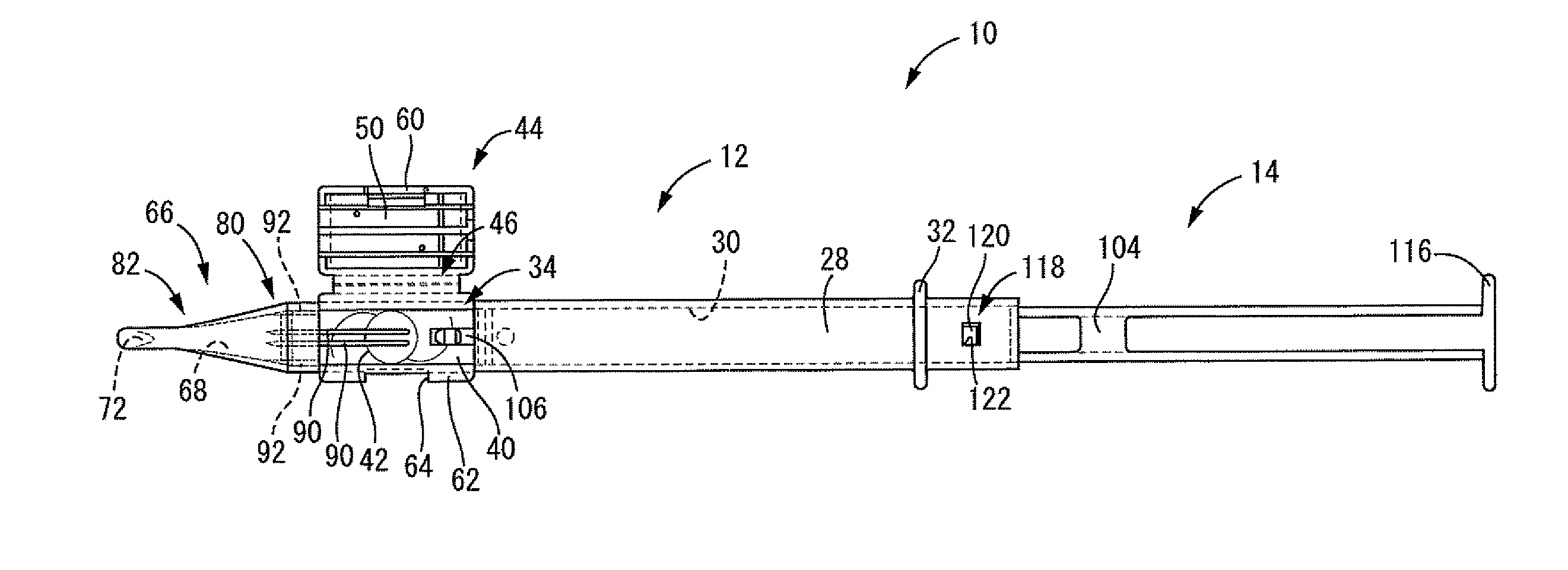
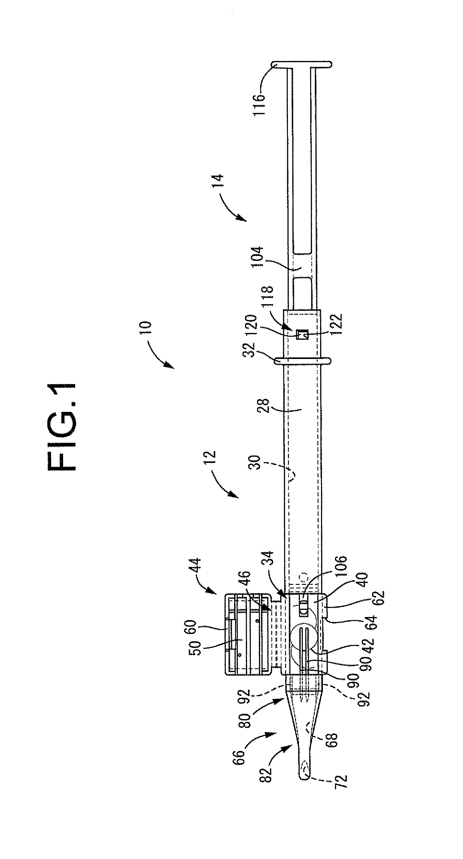
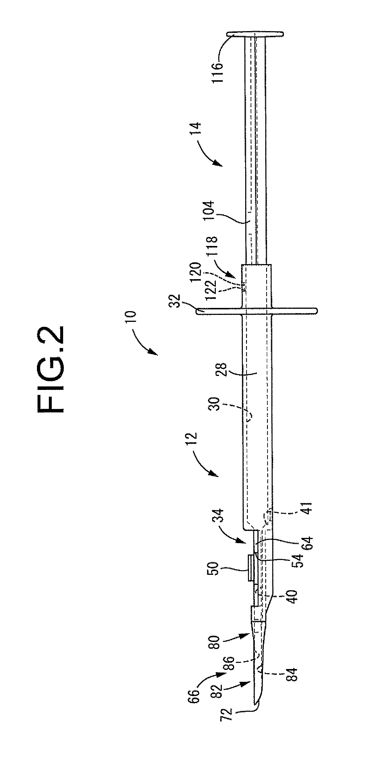
[0056]First of all, FIGS. 1 and 2 show an intraocular lens insertion tool 10 as one of the embodiments of this invention. The insertion tool 10 contains an intraocular lens 16 described later within a tool body 12 in an approximate shape of a cylinder with a pass-through hole inside and open front and back ends, and is configured with a plunger 14 inserted therein as a plunging member. In the following descriptions, the “front” of the insertion tool 10 means a direction in which the plunger 14 is pushed out (left side in FIG. 1), and the “up-down direction” means that of FIG. 2. In addition, the “left-right direction” means that of the insertion tool 10 seen from behind (up is right and down is left in FIG. 1), and the “width direction” means this left-right direction unless otherwise specified. Also, the “front” of the eye means the cornea side an...


PUM


Abstract

An intraocular lens insertion tool is presented. An introductory part in an insertion cylinder is provided, at a widthwise central portion of a bottom surface, with a central protrusion which extends in an axial direction of a tool body and protrudes toward an upper surface to get in contact with a center portion of a rear surface of an optical zone of an intraocular lens. The upper surface is provided, at its both widthwise ends, with a pair of lateral protrusions, which extend in the axial direction of the tool body and protrude toward the bottom surface to get in contact with both ends of a front surface of the optical zone of the intraocular lens. A lens pressing face of a plunging member is formed with a dimension spanning from the bottom surface to the upper surface at a tip end section of the insertion cylinder.

Description

TECHNICAL FIELD[0001]This invention relates to an intraocular lens insertion tool used for inserting an intraocular lens into the eye.BACKGROUND ART[0002]Conventionally, in cataract surgery and other operations, a method has been adopted wherein a crystalline lens is extracted and removed from the capsule through an incision made on ocular tissues such as the cornea (sclera) and anterior lens capsule, and thereafter, an intraocular lens is inserted into the eye via the above incision to be set in the capsule in lieu of the removed lens.[0003]In such operations using an intraocular lens, insertion tools for intraocular lenses such as those described in Patent Documents 1 and 2 are commonly used. In general, these insertion tools for intraocular lenses are used to place an intraocular lens within the lens capsule by means of inserting the tip opening of an insertion cylinder located at the tip of the tool body through an incision and pushing out the intraocular lens in a compactly def...

Claims


Application Information

Patent Timeline
IPC IPC(8): A61F9/007
CPCA61F2/167
Inventor NIWA, KAZUHARUTANAKA, MASAYOSHISUZUKI, YASUHIKO
Owner KOWA CO LTD
Why Eureka
Try Eureka