
Basin covering device

a technology of base covering and pool, which is applied in the direction of vessel hatches/hatchways, building components, vessel construction, etc., can solve the problems of depth and therefore the cost of this trench, and the general aesthetic appearance of the pool is affected, and the drawback is all the more detrimental

Inactive Publication Date: 2011-09-22
ABRISUD
View PDF8 Cites 2 Cited by
  • Summary
  • Abstract
  • Description
  • Claims
  • Application Information

AI Technical Summary

Benefits of technology

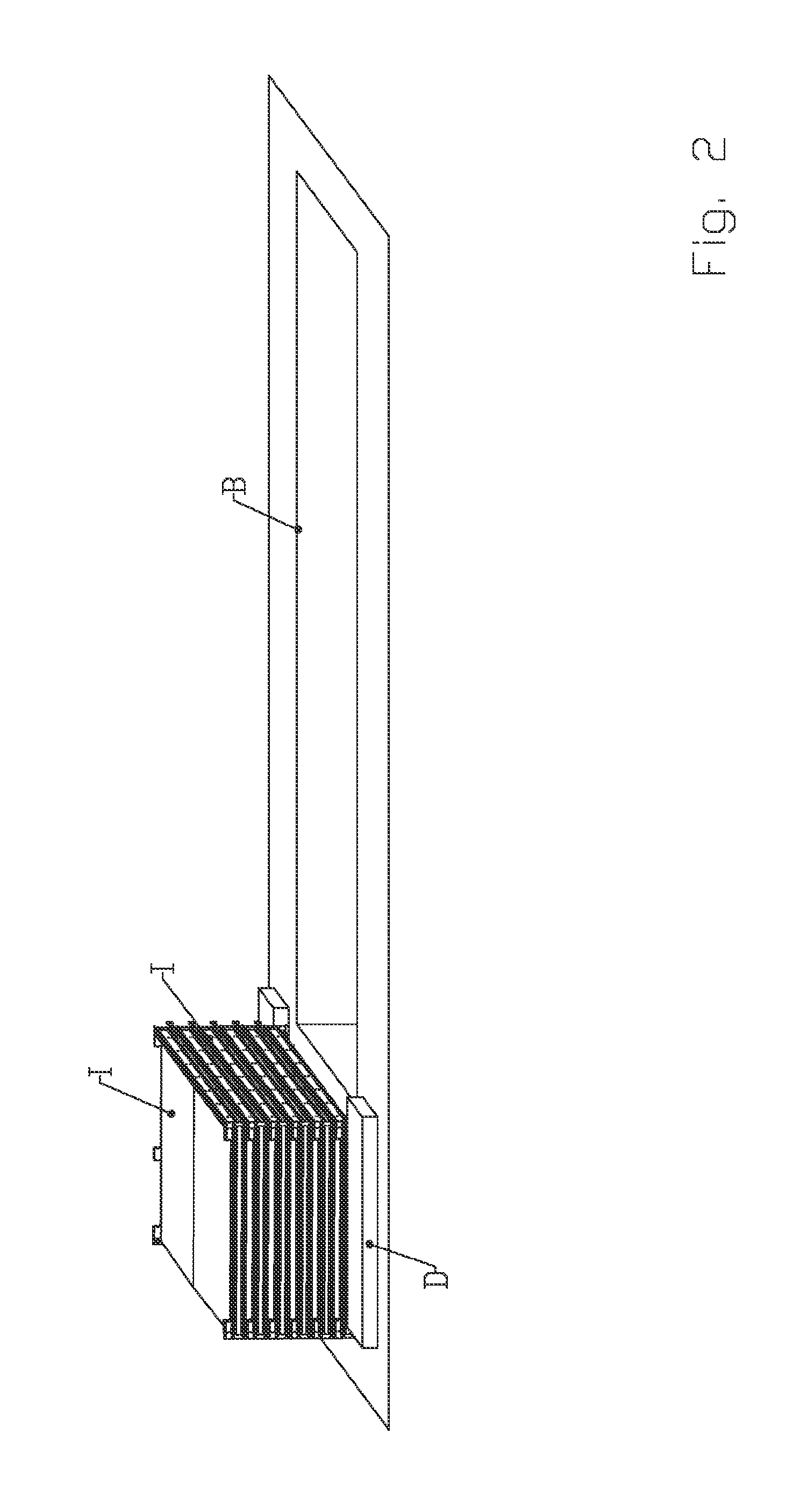
[0015]This feature is particularly advantageous in that it meets the objective of the invention, which is the reduction in the volume of the stacked roof elements by retraction of the running means during stacking thereof. Thus, whatever the height necessary between the roof element and the top rim of the pool, the height of the castor supports no longer participates in the height of the stack and therefore the volume thereof. The volume of such a stack is thus greatly reduced thereby.
[0029]The transverse profiles can be either curved, folded or rectilinear. Nevertheless, as explained above, the invention is particularly justified for a shelter adopting roof elements flattened in shape. However, the roof elements forming a support frame for filling panels that constitute large horizontal flat surfaces are liable to present difficulties for the discharge of surface water. With regard to the solution for retraction of the castor supports proposed by the invention, the applicant imagined a shelter where the rims of the roof elements are not of the same height so that the inclination created facilitates and orients the discharge of the water received by the roof element. Such a particularly judicious configuration would pose problems for a stacking solution because of an accumulated inclination whereas the retraction of the castor support allows flat stacking.

Problems solved by technology

The applicant found that, in the stacked position, said roof elements formed a not insignificant volume disposed conventionally at the end of the pool and liable to impair the general aesthetic appearance of the pool.
This drawback is all the more detrimental in a configuration where the roof elements have been chosen with a flattened shape to avoid an excessively large volume above the pool.
In addition, when the roof elements are stacked inside a trench provided for this purpose, the depth and therefore the cost of this trench would depend on the height of the volume formed by the stack of roof elements.
However, the edges that conventionally form the rim of the pools are liable to constitute an upwardly projecting volume requiring the running means to raise the roof elements with respect to the top rim of the pool.

Method used


Image

  • Basin covering device
  • Basin covering device
  • Basin covering device

Examples


Embodiment Construction

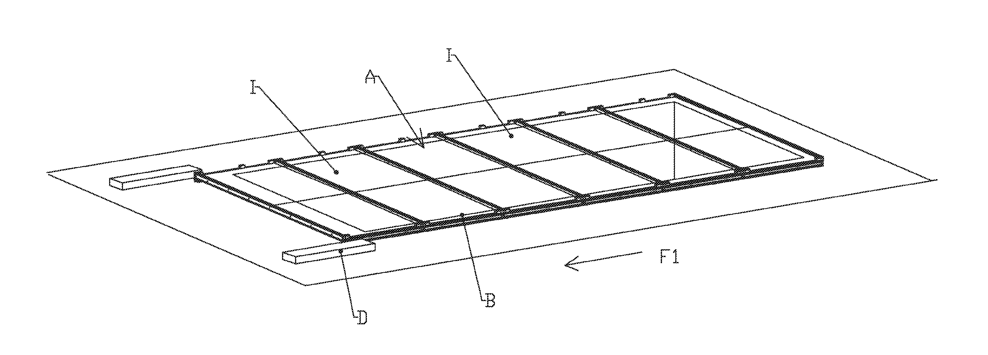
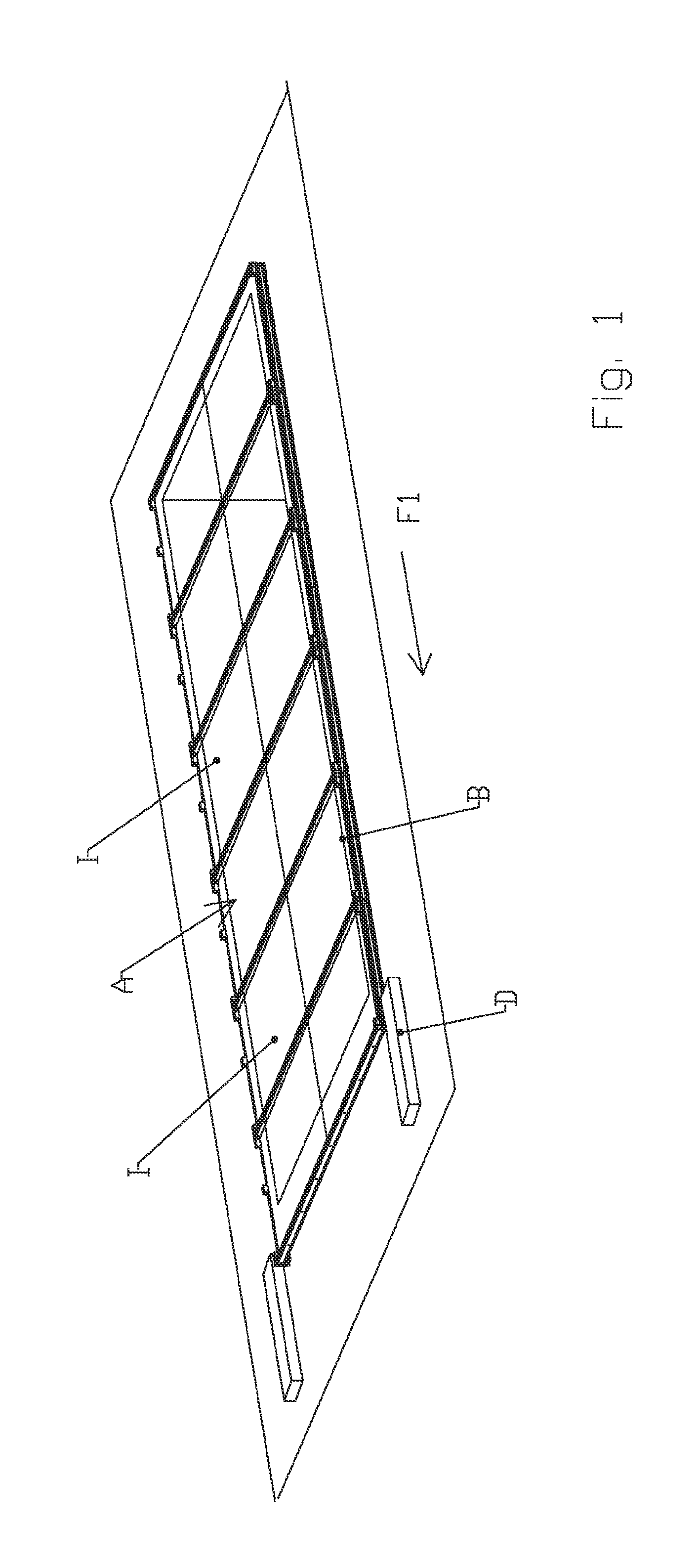
[0011]Noting this, the applicant carried out research on a shelter for a pleasure pool able to have a reduced volume in the stacked position. This research resulted in the design of a shelter for a pleasure pool of the swimming pool, spa, etc type which, formed by roof elements, is able to pass from a deployed position in which the roof elements are disposed juxtaposed and the pool is covered, to a stacked position where the roof elements are disposed one above the other and the pool is partially or completely uncovered,

[0012]said roof elements comprising two transverse profiles braced by longitudinal crossmembers with the so-called end crossmembers disposed at the ends of said profiles resting on the rim of the pool by means of running means that consist of castors,

[0013]which is remarkable in that

[0014]the castors are mounted on castor supports mounted foldably with respect to the end crossmembers so as to allow retraction thereof when the roof elements are stacked.

[0015]This feat...


PUM


Abstract

The invention relates to a shelter (A) for, for example, a pool- or spa-type recreational basin (B) that is formed of roofing elements (I) and is capable of passing from a deployed position, where the roofing elements are placed in a juxtaposed manner and the basin is covered, to a stacked position, where the roofing elements are placed one over the other and the basin is partially or completely uncovered, said roofing elements (I) including two transverse sections (110 and 120) cross-tied with longitudinal cross-pieces (130), with the so-called extreme cross-pieces (140 and 150) placed on the ends of said sections (110 and 120) that eventually rest on the rim of the basin (B) through a rolling means (300) that is formed of wheels (310) and remarkable in that the wheels (310) are mounted on wheel holders (320) that are foldably mounted relative to the extreme cross-pieces (140 and 150) so as to enable the folding away thereof during the stacking of the roofing elements (I).

Description

FIELD OF APPLICATION OF THE INVENTION[0001]The present invention relates to the field of pleasure pools such as those used for swimming pools, spas, etc, and in particular to adaptations enabling covering thereof under the best possible conditions.DESCRIPTION OF THE PRIOR ART[0002]There exist in the prior art shelters for pleasure pools such as those used for swimming pools, spas, etc, which, formed by roof elements, are able to pass from a deployed position where the roof elements are disposed juxtaposed and the pool is covered, to a stacked position where the roof elements are disposed one above the other and the pool is partially or completely uncovered.[0003]This passage from one configuration to another, which is of course reversible, is implemented by movement means, motorised or not. One example of a shelter and motorisation means implementing passage from an unfolded position to a deployed position and vice versa, is described in the document WO 2005 / 052285.[0004]The applica...

Claims


Application Information

Patent Timeline
IPC IPC(8): E04H4/08E04B7/16
CPCB61D39/002E04H4/086B63B19/19
Inventor POUTHE, CHRISTOPHETESTU, WILLIAMWYSTUP, FREDERIC
Owner ABRISUD
Learn More