
Distributor, and evaporator and refrigerating machine with the same

a technology of evaporator and distributor, which is applied in the direction of indirect heat exchangers, refrigeration components, lighting and heating apparatus, etc., can solve the problems of significant increase in circulation, unstable flow of cooling medium, and degradation of compressor performance due to liquid suction, so as to improve heat exchange efficiency and heat exchange performance of evaporator, the effect of stable flow

Inactive Publication Date: 2011-09-22
LG ELECTRONICS INC
View PDF8 Cites 27 Cited by
  • Summary
  • Abstract
  • Description
  • Claims
  • Application Information

AI Technical Summary

Benefits of technology

The patent describes an improved distributor for an evaporator and refrigerating machine. The distributor has a curved inner surface and multiple distribution holes that create a stable flow and steady circulation of the cooling medium as it flows from the condenser to the evaporator. This prevents bubbling and vibration in the cooling medium, which can improve the performance and efficiency of the refrigerating machine. Additionally, a perforated plate can be added to further enhance heat transfer efficiency. Overall, this patent provides a solution for improving the flow and circulation of the cooling medium in the evaporator and refrigerating machine.

Problems solved by technology

In the two-phase fluid cooling medium, the cooling medium in the gas state has much larger specific volume than the cooling medium in the liquid state, and a flow of the cooling medium in the liquid state is interfered with by the cooling medium in the gas state.
Therefore, the flow of the cooling medium is in unstable state, and the circulation is significantly amplified.
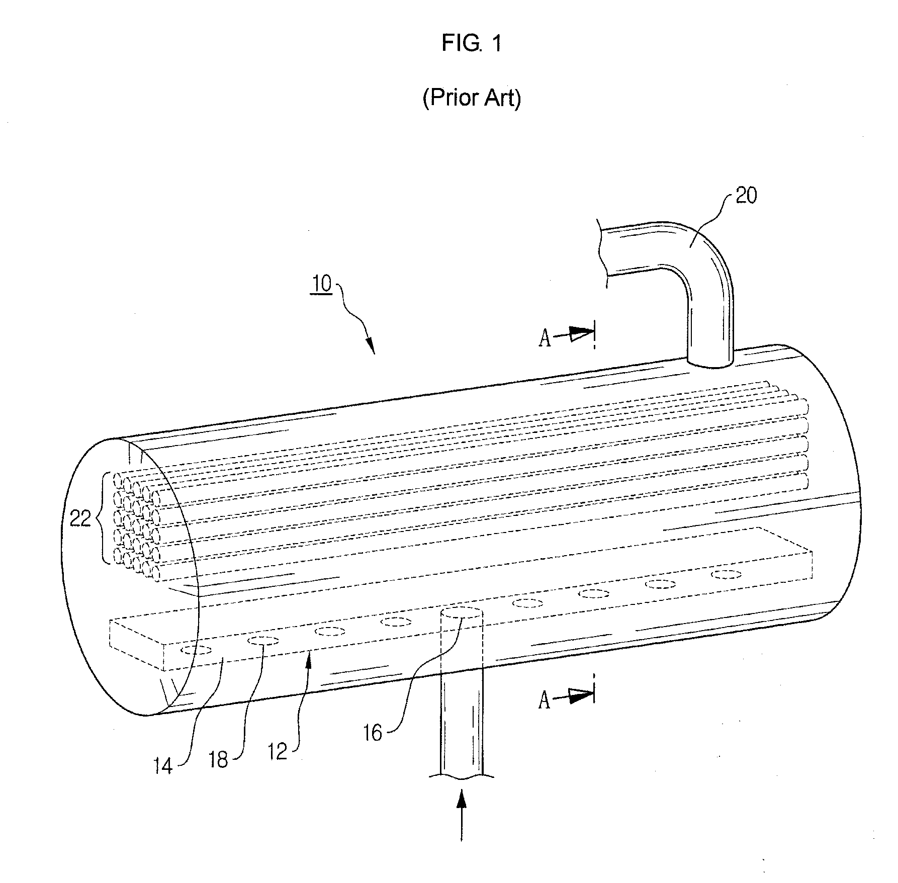
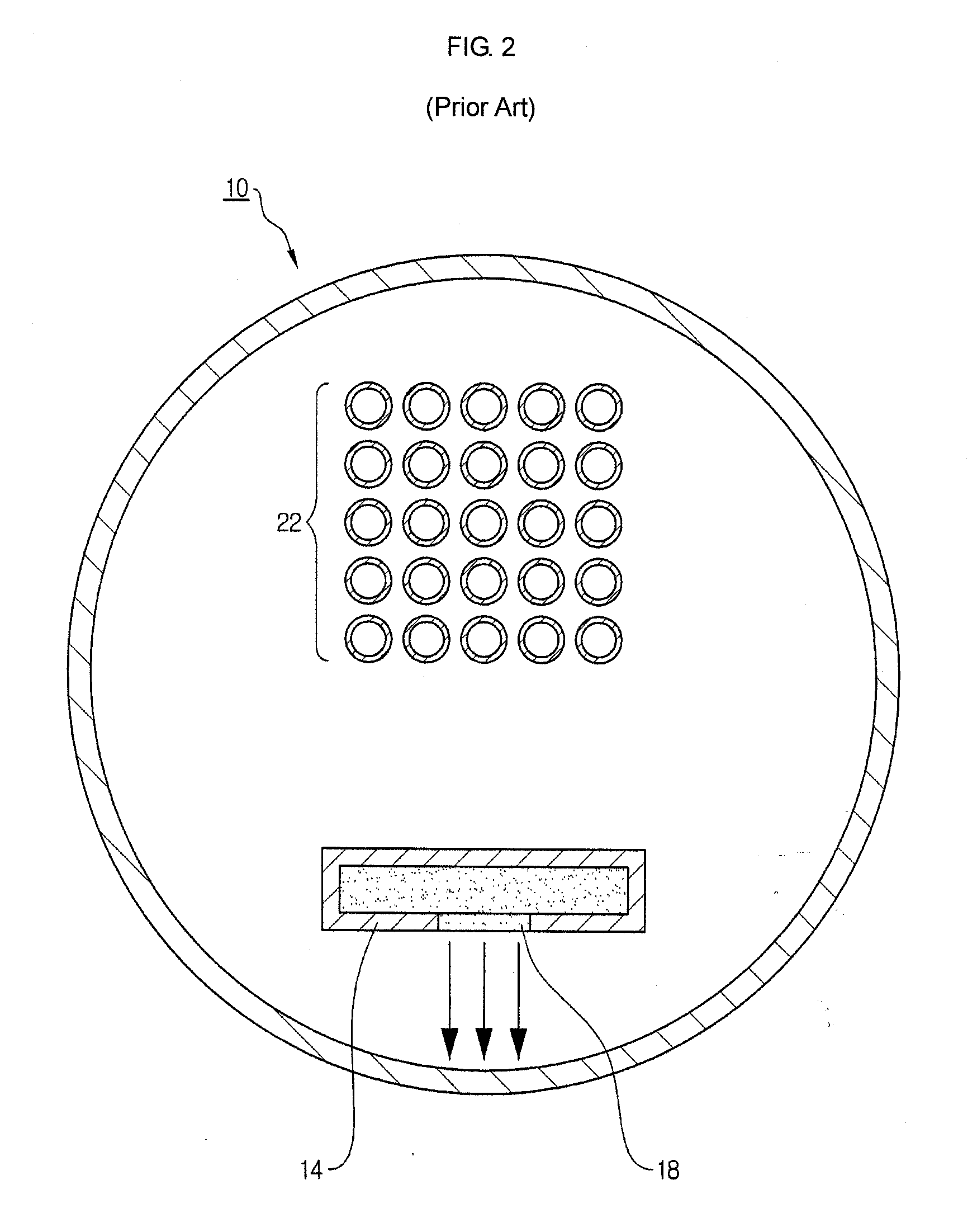
In addition, since the center of the distribution hole 18 faces the bottom of the evaporator directly below in the vertical direction, in a case where the cooling medium hits against the bottom of the evaporator, an influence of the collision becomes significant, and a liquid surface of the cooling medium of the evaporator fluctuates excessively.
During the suction of the cooling medium liquid and the bubbling liquid through a suction pipe 20, liquid suction into the compressor may result in degradation of the compressor performance.
Moreover, as bubbles are produced in the liquid surface of the cooling medium, heat transfer efficiency and heat exchange performance of the evaporator are further degraded.
As a result, in the existing distributor, due to the structural problems as described above, heat transfer efficiency and heat exchange performance of the evaporator are degraded, and the performance of the compressor is degraded due to excessive generation of bubbles and the liquid suction phenomenon.
Therefore, it is difficult to enhance the efficiency and performance of the refrigerating machine.

Method used


Image

  • Distributor, and evaporator and refrigerating machine with the same
  • Distributor, and evaporator and refrigerating machine with the same
  • Distributor, and evaporator and refrigerating machine with the same

Examples


Embodiment Construction

[0028]Exemplary embodiments now will be described more fully hereinafter with reference to the accompanying drawings, in which exemplary embodiments are shown. This disclosure may, however, be embodied in many different forms and should not be construed as limited to the exemplary embodiments set forth therein. Rather, these exemplary embodiments are provided so that this disclosure will be thorough and complete, and will fully convey the scope of this disclosure to those skilled in the art. In the description, details of well-known features and techniques may be omitted to avoid unnecessarily obscuring the presented embodiments.

[0029]The terminology used herein is for the purpose of describing particular embodiments only and is not intended to be limiting of this disclosure. As used herein, the singular forms “a”, “an” and “the” are intended to include the plural forms as well, unless the context clearly indicates otherwise. Furthermore, the use of the terms a, an, etc. does not de...


PUM


Abstract

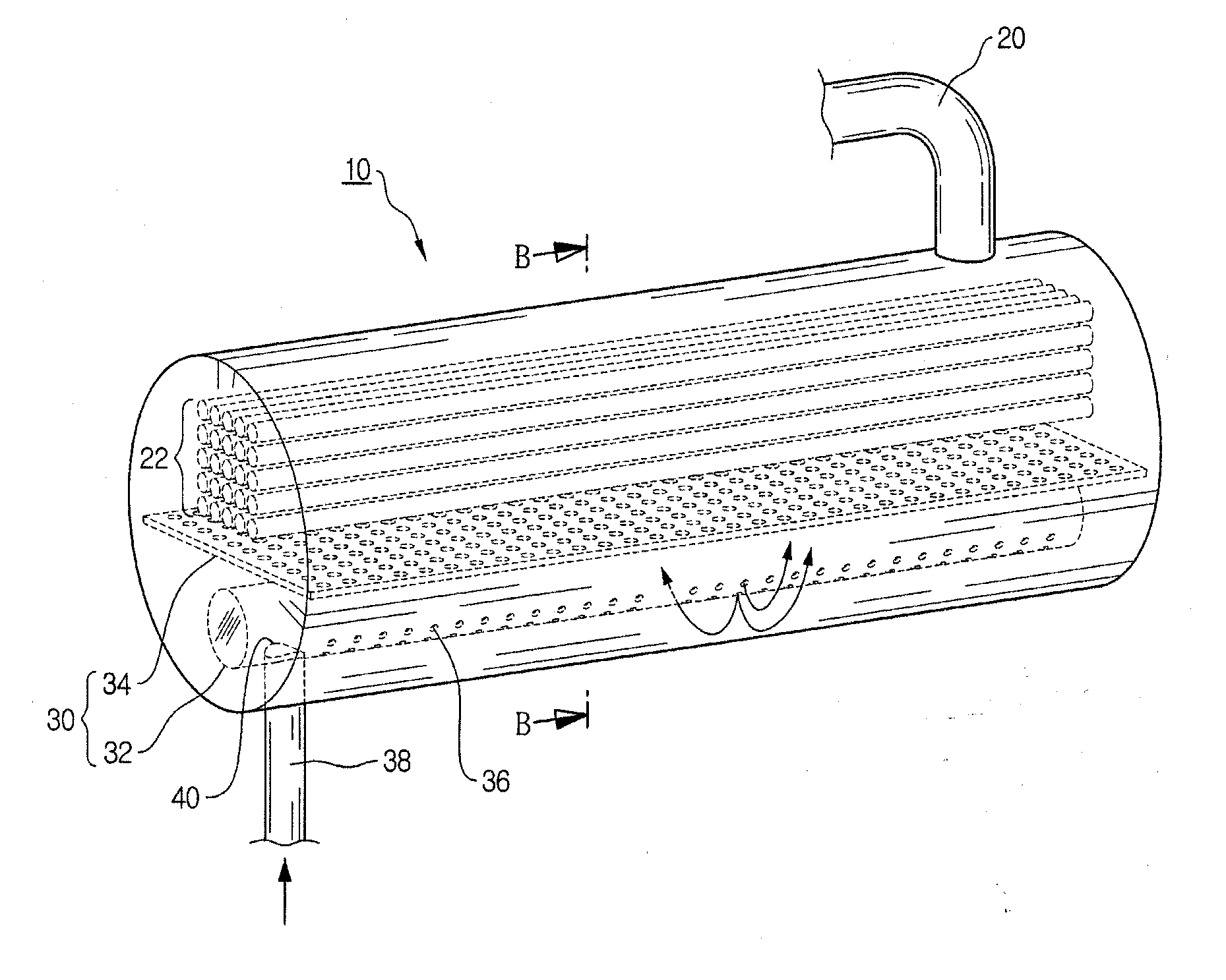
Provided are a distributor having a distribution tube having an inner surface formed as a curved surface, a plurality of distribution holes which are formed in a lower semicircular region of the distribution tube with respect to a horizontal line of the distribution tube and are arranged to be symmetrical about a vertical line of the distribution tube and a connection hole provided in the distribution tube so that the distribution tube is connected to a connection tube, an evaporator and a refrigerating machine with the distributor. A perforated plate may be fixed to an inside of the distribution tube so as to block a flow path of a cooling medium.

Description

CROSS-REFERENCE TO RELATED APPLICATION[0001]This application claims priority to Korean Patent Application No. 10-2010-0023686, filed on Mar. 17, 2010, and all the benefits accruing therefrom under 35 U.S.C. §119, the contents of which in its entirety are herein incorporated by reference.BACKGROUND[0002]1. Field[0003]This disclosure relates to a distributor, and an evaporator and a refrigerating machine with the distributor, and more particularly, to a distributor which is improved to cause a cooling medium to form a stable flow and a steady circulation when flowing from a condenser into an evaporator, and an evaporator and a refrigerating machine with the distributor.[0004]2. Description of the Related Art[0005]In general, a vapor-compression refrigerating machine is composed of a compressor, a condenser, an expansion valve, and an evaporator. To roughly describe a refrigeration cycle of such a vapor-compression refrigerating machine, a cooling medium in a gas state is compressed to...

Claims


Application Information

Patent Timeline
Patent Type & Authority Applications(United States)
IPC IPC(8): F25B1/00F25B39/02
CPCF25B39/028F25B2339/0242F28F9/0278F28D2021/0071F28F9/0273F28D7/163
Inventor LEE, HYUNG JUN
Owner LG ELECTRONICS INC
Learn More