
Heat exchanger

a heat exchanger and heat exchanger technology, applied in the direction of heat exchange apparatus, heat exchanger conduits, corrosion prevention, etc., can solve the problem of promoting turbulence in the heat exchanger

Inactive Publication Date: 2011-09-22
ROCORE UK
View PDF8 Cites 3 Cited by
  • Summary
  • Abstract
  • Description
  • Claims
  • Application Information

AI Technical Summary

Benefits of technology

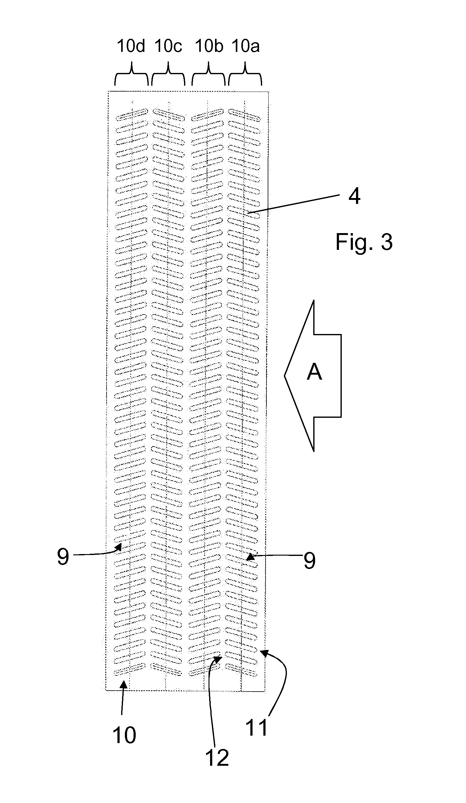
[0008]This is advantageous as the arrangement of heat transfer tubes promotes efficient heat transfer to the heat removal fluid without the need for fins. The undulating path followed by the heat removal fluid results in increased contact between the fluid and the heat transfer tubes and also promotes turbulence within the heat exchanger. It has been found that this arrangement is sufficiently efficient to obviate the need for fins. The heat transfer tubes can be substantially smooth and shaped to cause the heat removal fluid to follow the undulating path. As the undulating path is provided by the shape or arrangement of the walls of the heat transfer tubes rather than by any fins or projections, the heat transfer tubes gather little dirt and debris and are easily cleaned.
[0010]Thus, the director surfaces of each stack or row are arranged to change the direction of the flow of the heat removal fluid, which promotes heat transfer to the heat removal fluid. This is thought to be due to the creation of turbulence between the heat transfer tubes and between the stacks or rows, which improves the contact of the heat removal fluid with the heat transfer tubes and therefore enhances the transfer of heat between the heat transfer fluid and the heat removal fluid. As the heat exchanger does not require fins, it is significantly more reliable, as debris cannot collect within the radiator thus maintaining a good flow of heat removal fluid. It is also easy to clean.
[0014]In particular, the inclination of the director surfaces and the arrangement of the stacks are preferably such that a tangent to the director surface of a tube in the first stack falls upon the director surface of a tube in an adjacent stack. This helps promote the undulating flow path through the heat exchanger and therefore the turbulance.

Problems solved by technology

The undulating path followed by the heat removal fluid results in increased contact between the fluid and the heat transfer tubes and also promotes turbulence within the heat exchanger.

Method used


Image

  • Heat exchanger
  • Heat exchanger
  • Heat exchanger

Examples


Embodiment Construction

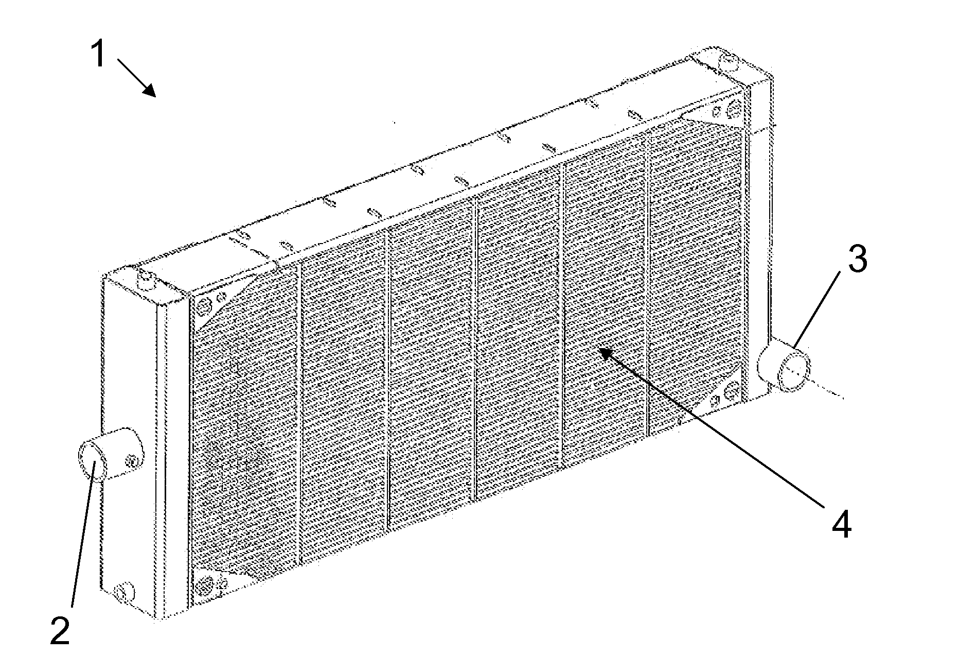
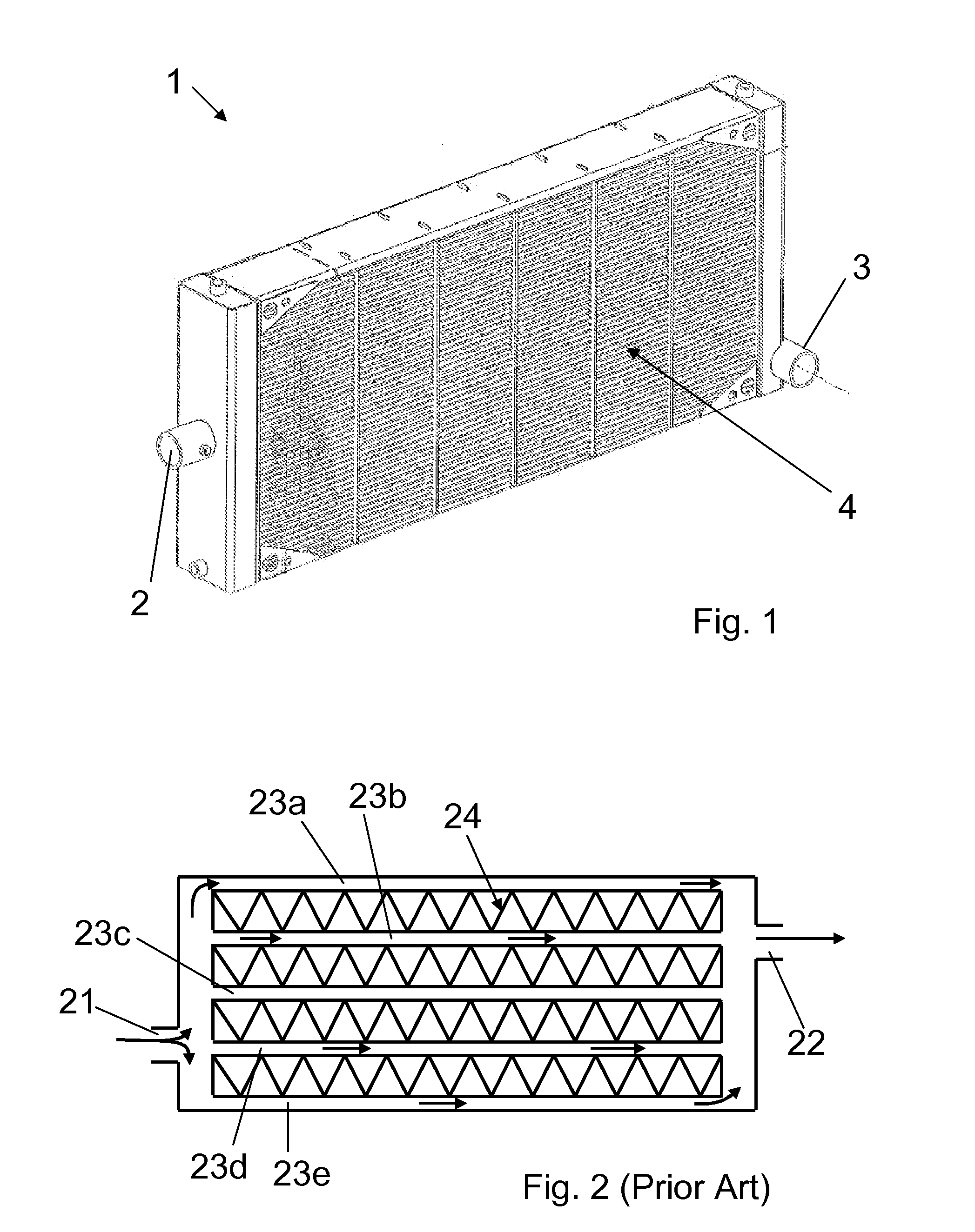
[0023]The heat exchanger of the embodiment shown in FIG. 1 is specifically a radiator 1 for cooling a train diesel engine. A heat transfer fluid, which in this embodiment is a water based coolant, is pumped through the engine to absorb the heat generated thereby. The radiator 1 is mounted at the side of the train perpendicular to the direction of travel. A fan is used to cause atmospheric air, which is the heat removal fluid, to flow through the radiator to remove the heat to atmosphere.

[0024]The radiator 1 comprises an inlet 2 to receive the coolant from the engine. An outlet 3 returns the coolant, once cooled by its passage through the radiator 1, to the engine water jackets and pipework for recirculation. The radiator 1 includes a plurality of heat transfer tubes 4 that connect the inlet 2 and outlet 3. Thus, the coolant received at the inlet 2 passes through a distributor or inlet header, which distributes the coolant into the heat transfer tubes 4. The coolant flows through the...


PUM


Abstract

A heat exchanger comprising a plurality of heat transfer tubes adapted to transport heat transfer fluid from an inlet to an outlet, the heat transfer tubes comprising elongate hollow members adapted to receive the heat transfer fluid therein, the heat exchanger adapted to receive a flow of heat removal fluid flow between the heat transfer tubes, wherein the heat transfer tubes are arranged such that the heat removal fluid is caused to follow a substantially undulating path through the heat exchanger.

Description

CROSS-REFERENCE TO RELATED APPLICATIONS[0001]This application claims the benefit of U.S. Patent Application No. 61 / 315,559 filed 19 Mar. 2010, entitled “Heat Exchanger” and which is hereby incorporated by reference in its entirety.FIELD OF THE INVENTION[0002]This invention relates to a heat exchanger. In particular, it relates to a radiator for cooling a power plant or engine, such as a train engine, and more particularly to a finless radiator for cooling an engine.BACKGROUND[0003]A heat exchanger that is used to cool a vehicle engine is typically called a radiator. A heat transfer fluid is passed through the engine to absorb the heat generated by the engine. The heated transfer fluid is then passed through radiator tubes within the radiator, which transfers the heat of the heat transfer fluid to a heat removal fluid. The heat removal fluid is usually atmospheric air, which flows over the radiator tubes and absorbs the heat from the heat transfer fluid flowing therein and dissipates...

Claims


Application Information

Patent Timeline
Patent Type & Authority Applications(United States)
IPC IPC(8): F28D1/00
CPCF28D2021/0094F28D1/05383F28F19/00F28F2210/00
Inventor SALTER, KEVIN
Owner ROCORE UK
Learn More