Log periodic antenna and manufacturing method thereof

Inactive Publication Date: 2011-09-22
MENIX +1
View PDF5 Cites 5 Cited by
  • Summary
  • Abstract
  • Description
  • Claims
  • Application Information

AI Technical Summary

Benefits of technology

[0019]The present invention including the above-described features enables the antenna to have the simple structure. Also, the present invention enables the antenna to cover the various designs of the log periodic antenna, because the signal pattern 300 and the grounds pattern 500 are fixed to the pattern receiving surface 110 by attachment and because the signal pattern 300 and the ground pattern 500 are readily

Problems solved by technology

The antenna made of the rod-type element has the disadvantages in that it is heavy and weak to the external impact because the rod is made from aluminum or stainless steel.
Further, a pattern printing, which is deemed to be d

Method used


Image

  • Log periodic antenna and manufacturing method thereof
  • Log periodic antenna and manufacturing method thereof
  • Log periodic antenna and manufacturing method thereof

Examples


Embodiment Construction

[0028]Hereinafter, a preferred embodiment of the present invention will be described with reference to the accompanying drawings. In the following description and drawings, the same reference numerals are used to designate the same or similar components, and so repetition of the description on the same or similar components will be omitted.

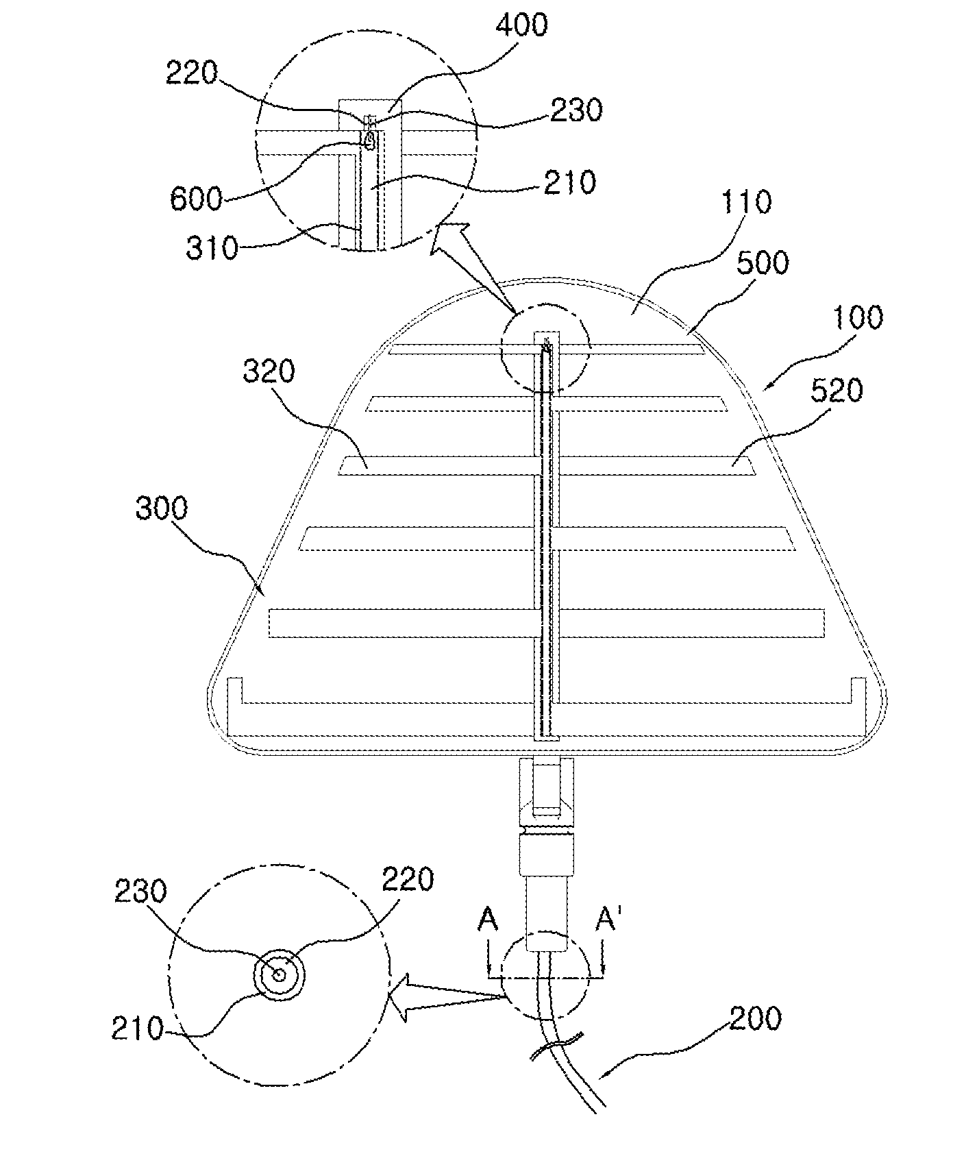
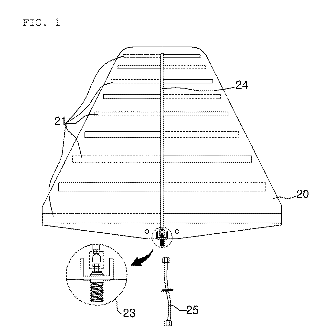
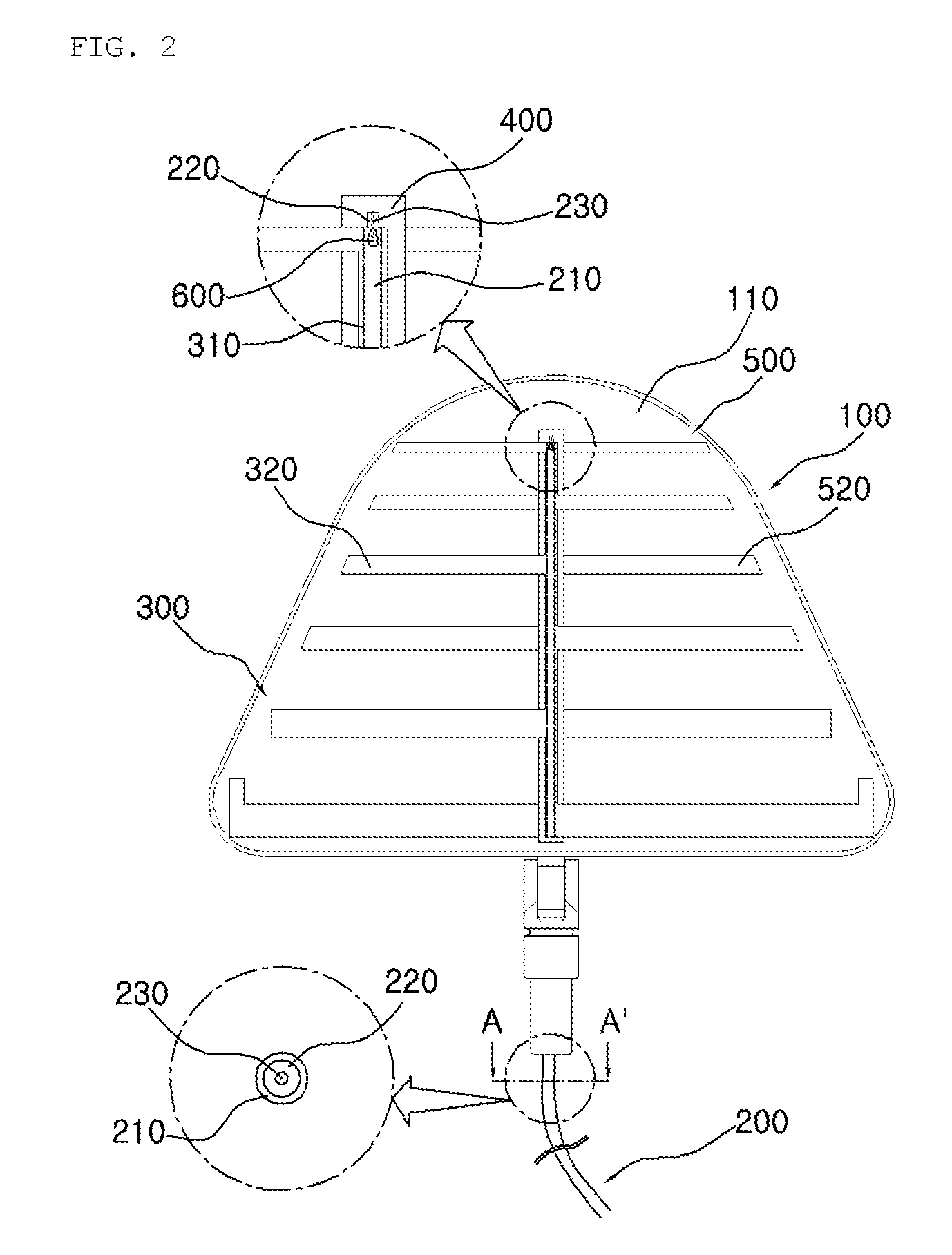
[0029]FIG. 1 is the bottom view of the log periodic antenna according to the prior art. FIG. 2 is the plan view and the enlarged view of the log periodic antenna according to an embodiment of the present invention. FIG. 3 is the perspective view and the enlarged view of the log periodic antenna according to the embodiment of the present invention. FIG. 4 is the perspective view illustrating a process of assembling the log periodic antenna according to the embodiment of the present invention. FIG. 5 is the enlarged views illustrating circles indicated with “B” and “C” in FIG. 4.

[0030]Referring to FIGS. 2 to 5, the log periodic antenna according to ...


PUM


Abstract

Disclosed is a log periodic antenna and a manufacturing method thereof. In the log periodic antenna, antenna elements are attached to an antenna body to thereby simplify a structure of the antenna, the antenna can be manufactured in various designs without restriction to the configuration of the antenna, and the number of contacting points between the antenna element and a feeder is minimized to thereby simplify the manufacturing process. By the antenna, it is possible to produce the log periodic antenna of the simple structure and of various designs without the restriction to the antenna configuration by attaching the signal pattern and ground pattern to the pattern receiving surface.

Description

BACKGROUND OF THE INVENTION[0001]1. Field of the Invention[0002]The present invention relates to a log periodic antenna and a manufacturing method thereof, and more particularly to a log periodic antenna and a manufacturing method thereof that make antenna elements attached to an antenna body to thereby simplify a structure of the antenna, that enable the antenna to be manufactured in various designs without restriction to the configuration of the antenna, and that make the number of contacting points between the antenna element and a feeder to be minimized to thereby simplify the manufacturing process.[0003]2. Description of the Prior Art[0004]As generally known in the art, the log periodic antenna is a broadband antenna wherein the length ratio and the interval ratio of adjacent antenna elements are constant and wherein it has almost constant frequency response within the frequency range of the longitudinal-type antenna row.[0005]The log periodic antenna is being widely used for r...

Claims


Application Information

Patent Timeline
IPC IPC(8): H01Q11/10H01P11/00
CPCY10T29/49018H01Q11/105
Inventor KIM, KEYNG HUNPARK, SEUNG KYOKIM, CHAN KUK
Owner MENIX
Why Eureka
Try Eureka