Tool joint

Inactive Publication Date: 2011-09-22
SU CHENG WEI
View PDF10 Cites 14 Cited by
  • Summary
  • Abstract
  • Description
  • Claims
  • Application Information

AI Technical Summary

Benefits of technology

[0007]The primary objective of the present invention is to provide a tool joint whose applicability is enhanced due to two operation modes.

Problems solved by technology

However, the above tool joint still suffers from the following defects in actual application:

Method used


Image

  • Tool joint
  • Tool joint
  • Tool joint

Examples


first embodiment

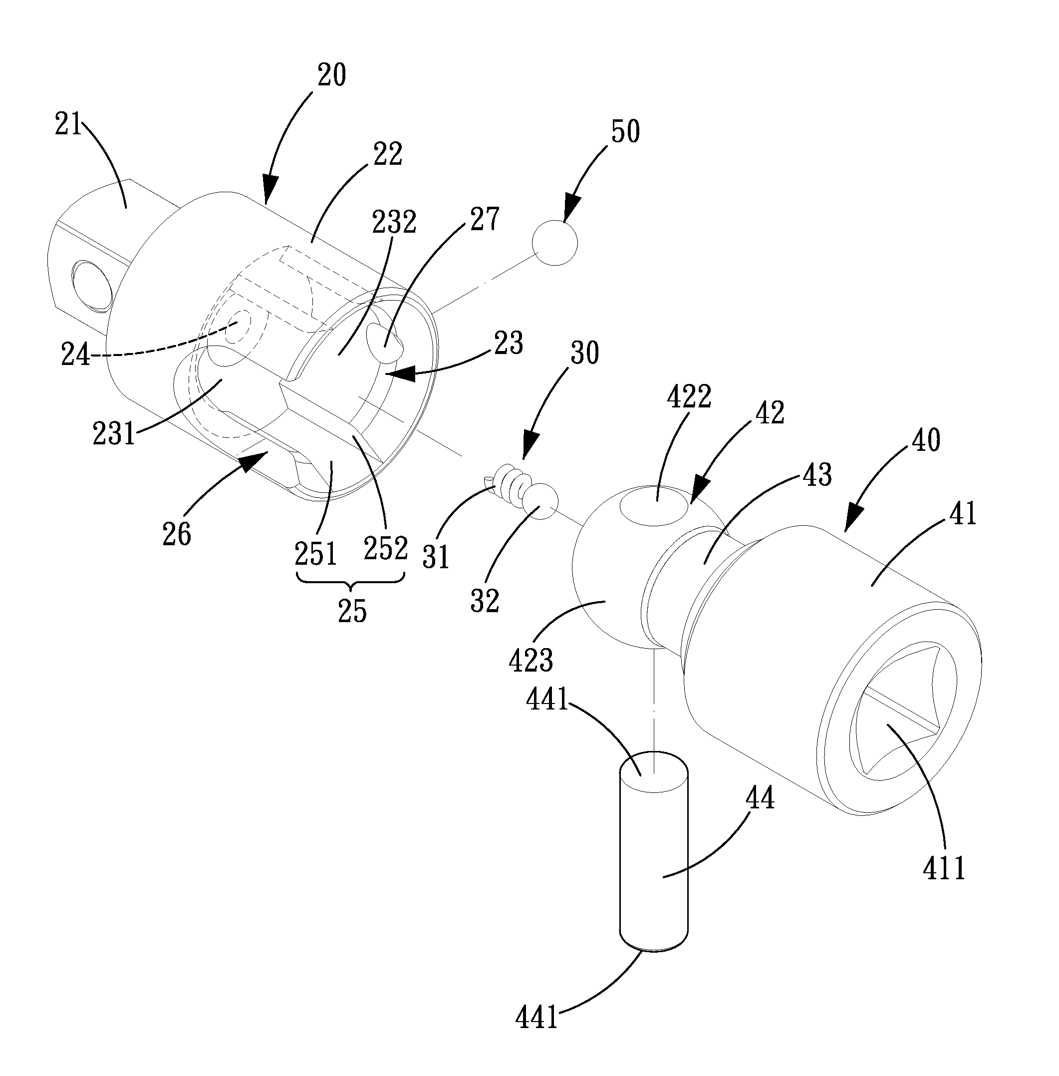
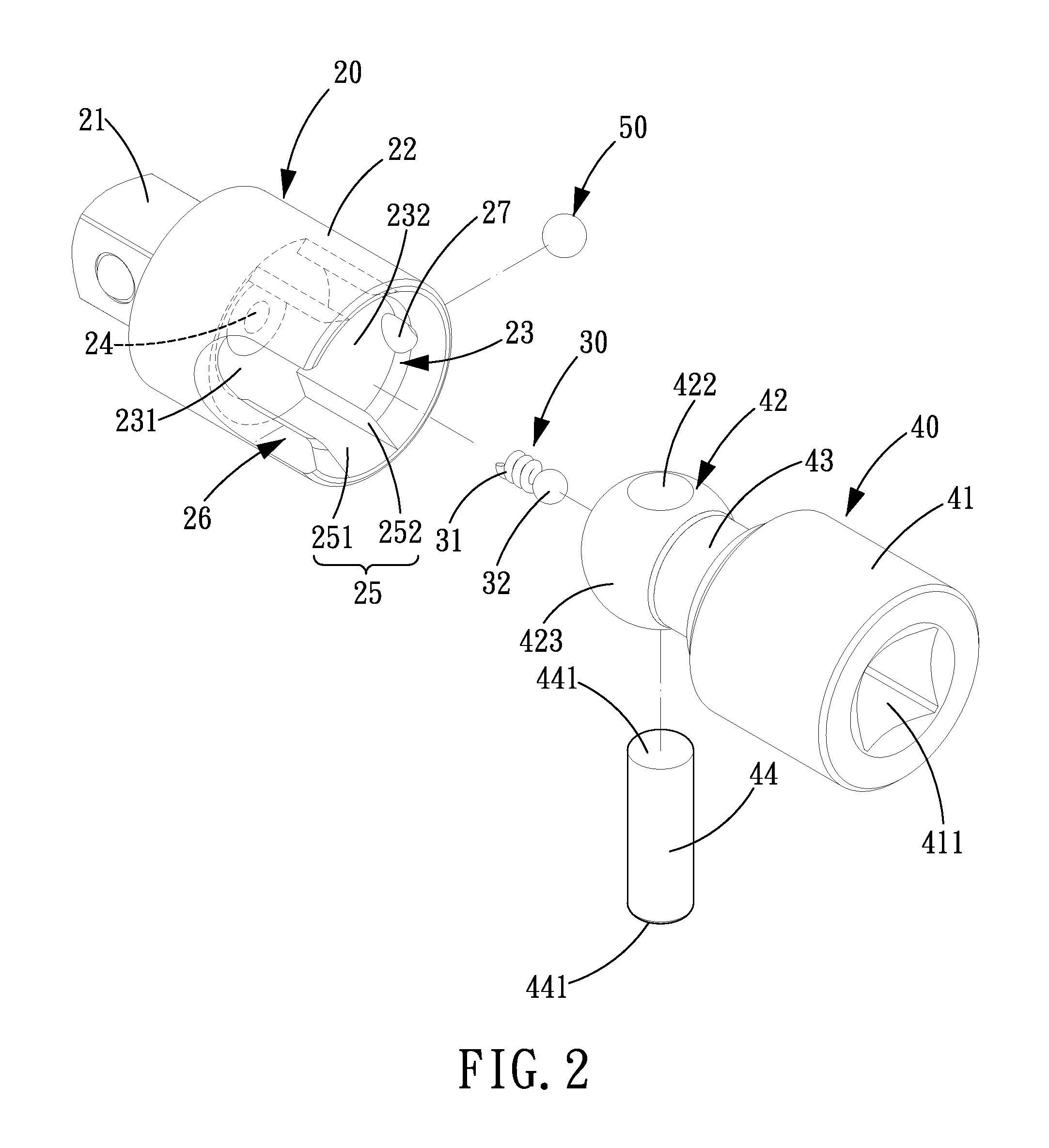
[0028]Referring to FIGS. 2-5, a tool joint in accordance with the present invention comprises a first rod 20, a pressing assembly 30, a second rod 40 and a positioning element 50.

[0029]The first rod 20 includes a first working portion 21 and a pivoting portion 22 at both ends thereof. The first working portion 21 is cylinder-shaped and adapted to be engaged with a socket 61. The pivoting portion 22 is formed with a pivoting groove 23 in an axial direction of the first rod 20. The pivoting groove 23 includes a receiving groove 24 in a bottom surface 231 thereof. The pivoting groove 23 is further formed with two limiting grooves 25 in an inner peripheral surface 232 thereof in the axial direction of the first rod 20. The respective limiting grooves 25 are defined by a bottom surface 251 and two side surfaces 252 connected to both ends of the bottom surface 251. Between the two limiting grooves 25 is formed a notch 26. The pivoting portion 22 includes a through hole 27 which is located...

second embodiment

[0042]Referring to FIG. 9, preferably, the present invention provides a tool joint in accordance with a second embodiment in which a first rod 20 including an engaging groove 211 in a first working portion 21, and a second rod 40 including a cylinder-shaped second working portion 41, and the engaging groove 211 of the first rod 20 is adapted for insertion of the drive tool 62 while the second working portion 41 of the second rod 40 is adapted for engagement with a socket 61.

third embodiment

[0043]Referring to FIG. 10, preferably, the present invention provides a tool joint in accordance with a third embodiment in which a bolt 44 is integrally formed on the ball portion 42 of the second rod 40 and has both ends 441 protruding from the outer peripheral surface 423 of the ball portion 42. The two ends 441 are disposed in the two limiting grooves 25 of the first rod 20 in the same manner.


PUM


Abstract

A tool joint comprises a first rod, a pressing assembly, a second rod and a positioning element. Through a notch formed in the first rod, the first rod can be adjusted to be vertical to the second rod, thus increasing one driving method of the second rod with respect to the first rod. Thereby, the tool joint includes two operation modes, enhancing the applicability.

Description

BACKGROUND OF THE INVENTION[0001]1. Field of the Invention[0002]The present invention relates to a tool capable of being adjusted to various working angle, and more particularly to a tool joint.[0003]2. Description of the Prior Art[0004]Referring to FIG. 1, a conventional tool joint capable of being adjusted to any angle comprises a first rod 11 and a second rod 12 that are pivoted to each other. The first rod 11 has an end 111 adapted to be drivingly connected to a drive tool (not shown) which may be a pneumatic tool or a ratchet wrench. The second rod 12 has an end 121 adapted to be engaged with a socket (not shown). The drive tool can drive the socket at various angles through the tool joint, enhancing convenience in use while widening the applicability range. However, the above tool joint still suffers from the following defects in actual application:[0005]When in use, the drive tool directly drives the first rod to rotate through the tool joint, and then the first rod 11 will d...

Claims


Application Information

Patent Timeline
IPC IPC(8): F16C11/06
CPCB25B13/48B25B15/001Y10T403/32631F16D3/2052B25B23/0028
Inventor SU, CHENG-WEI
Owner SU CHENG WEI
Why Eureka
Try Eureka