
Control device and control method for automatic transmission

a control device and automatic transmission technology, applied in the direction of gearing details, vehicle sub-unit features, transportation and packaging, etc., can solve the problems of difficult to prevent the reduction of discharge pressure, difficult to control the rotation speed of mechanical oil pumps individually, etc., to suppress the effect of suppressing the reduction of the discharge pressure of mechanical oil pumps

Active Publication Date: 2011-09-22
JATCO LTD +1
View PDF8 Cites 8 Cited by
  • Summary
  • Abstract
  • Description
  • Claims
  • Application Information

AI Technical Summary

Benefits of technology

[0008]An electric oil pump is driven by a motor, and therefore the rotation speed of the electric oil pump can be controlled freely. However, in the case of a mechanical oil pump driven by rotation generated by an engine or the like, for example, it is difficult to control the rotation speed of the mechanical oil pump individually, and it is therefore difficult to prevent the reduction in discharge pressure described above.
[0009]This invention has been designed to solve these problems, and an object thereof is to suppress a reduction in a discharge pressure of a mechanical oil pump caused by the intermixing of air into working oil.
[0012]According to these aspects, the flow control mechanism can be operated normally even when air is mixed into the working oil, and therefore a reduction in the discharge pressure of the mechanical oil pump can be suppressed.
[0013]According to this invention, a reduction in the discharge pressure of a mechanical oil pump can be suppressed even when air is mixed into working oil.

Problems solved by technology

However, in the case of a mechanical oil pump driven by rotation generated by an engine or the like, for example, it is difficult to control the rotation speed of the mechanical oil pump individually, and it is therefore difficult to prevent the reduction in discharge pressure described above.

Method used


Image

  • Control device and control method for automatic transmission
  • Control device and control method for automatic transmission
  • Control device and control method for automatic transmission

Examples


first embodiment

[0022]this invention will be described below with reference to the figures.

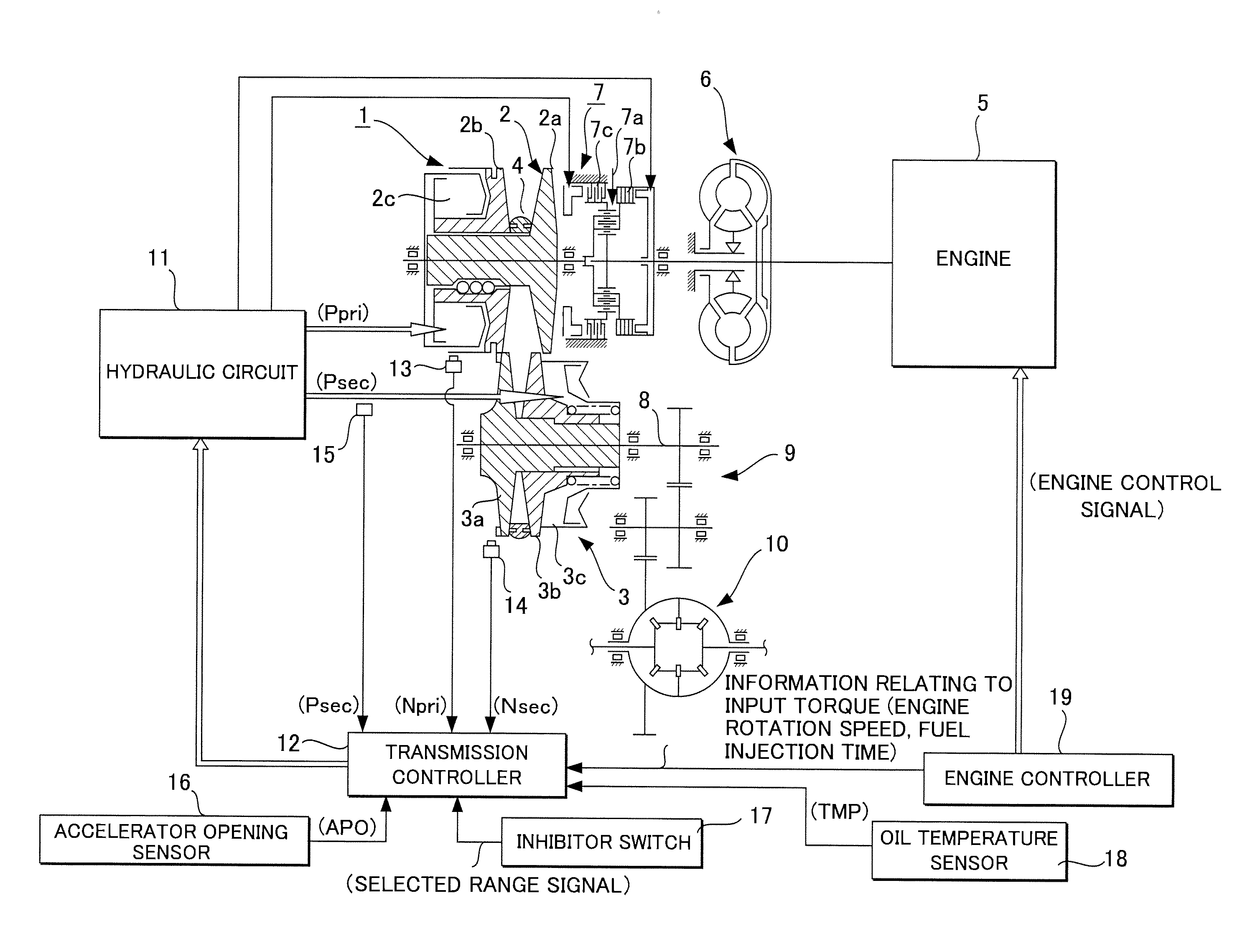
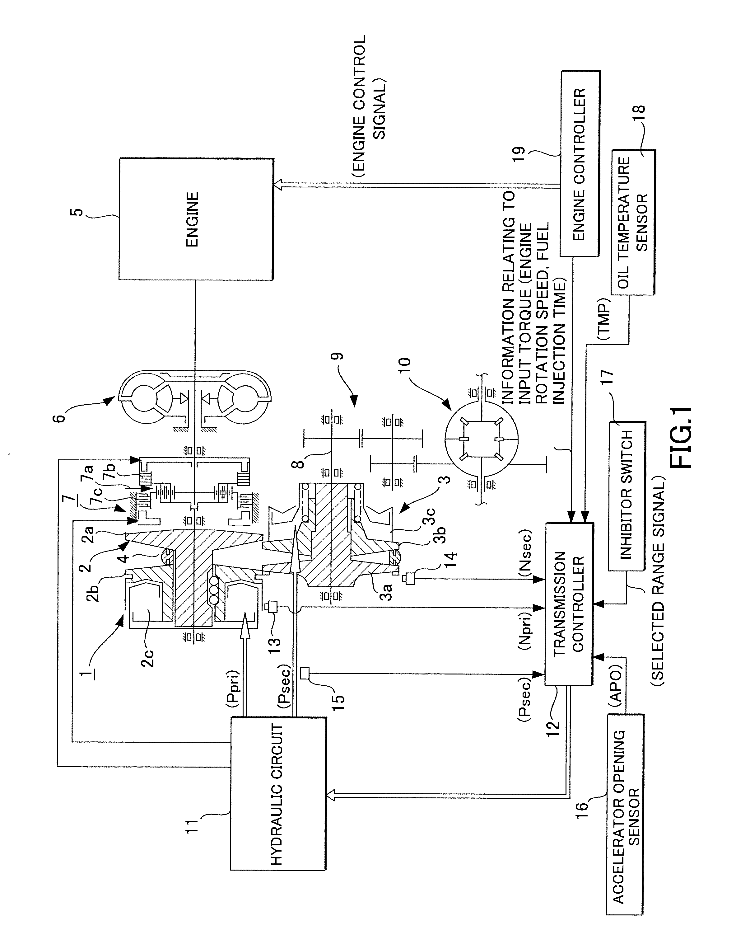
[0023]FIG. 1 shows an example of a control device for an automatic transmission according to the first embodiment of this invention. The automatic transmission shown in the figure is a V belt continuously variable transmission 1. In the V belt continuously variable transmission 1, a primary pulley 2 and a secondary pulley 3 are disposed such that respective V grooves thereof are in alignment, and a V belt 4 is wound around the V grooves of the pulleys 2, 3. An engine 5 serving as a drive source is disposed coaxially with the primary pulley 2, and a lockup torque converter 6 and a forward / reverse change-over mechanism 7 are provided between the engine 5 and the primary pulley 2 in sequence from the engine 5 side.

[0024]The forward / reverse change-over mechanism 7 has a double pinion planetary gear set 7a as a main constitutional element, a sun gear of which is coupled to the engine 5 via a torque converter 6 and...

second embodiment

[0073]Next, this invention will be described.

[0074]Oil pressure control executed in the second embodiment differs from that of the first embodiment. Here, differences with the first embodiment will be described.

[0075]The oil pressure control according to this embodiment will be described using FIG. 7.

[0076]Control executed from a step S200 to a step S203 is identical to that of the steps S100 to S103 of the first embodiment, and therefore description thereof has been omitted.

[0077]In a step S204, a determination is made as to whether or not the engine rotation speed is equal to or higher than a predetermined rotation speed. When the engine rotation speed is equal to or higher than the predetermined rotation speed, the routine advances to a step S205, and when the engine rotation speed is lower than the predetermined rotation speed, the routine advances to a step S207. The predetermined rotation speed is an engine rotation speed at which the differential pressure between the oil pres...


PUM


Abstract

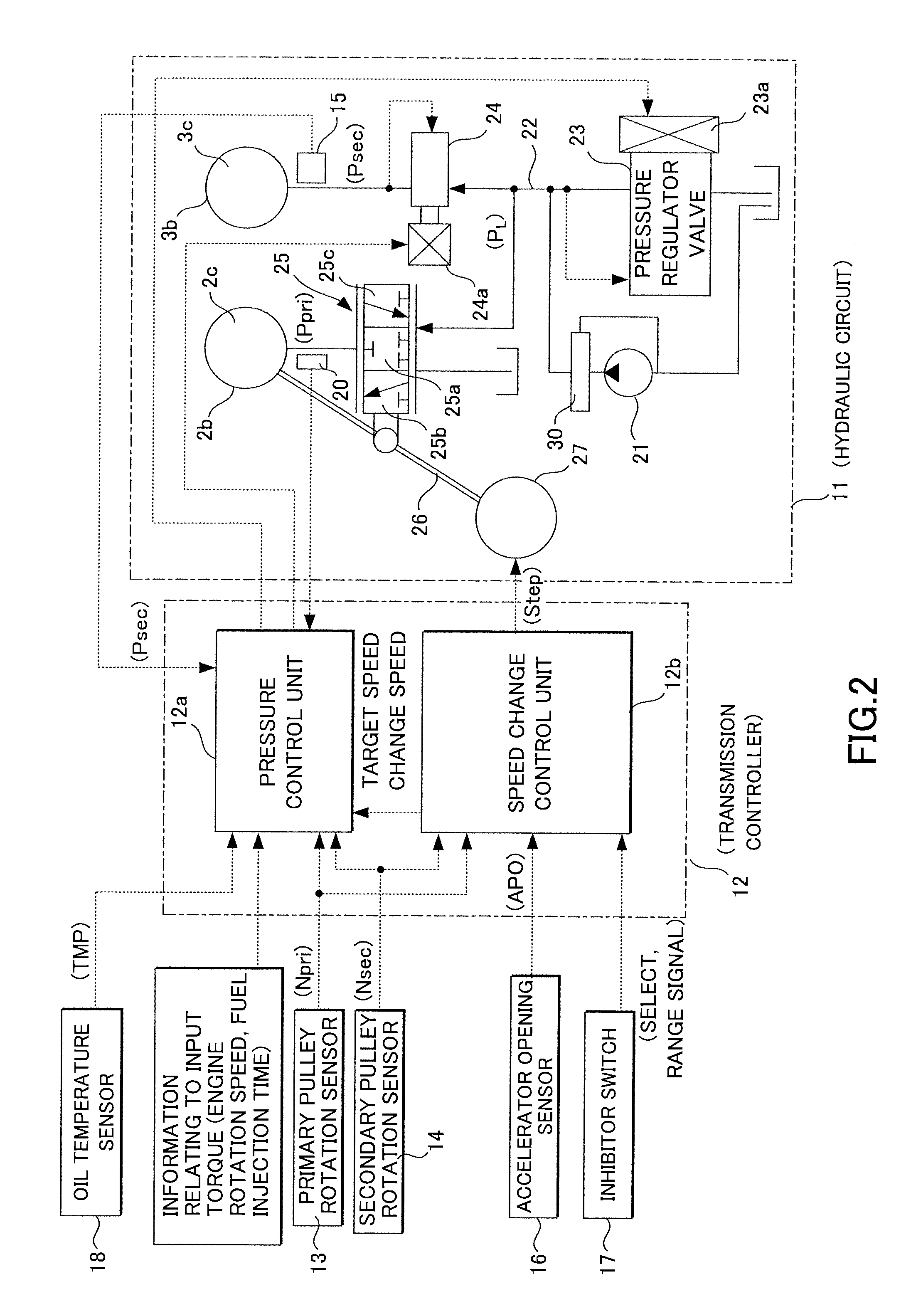
In a control device for an automatic transmission having a flow control mechanism that causes a part of a working oil discharged from a mechanical oil pump to flow into the mechanical oil pump when a differential pressure between an upstream side and a downstream side of a narrowed portion increases beyond a predetermined value, the narrowed portion being provided in a discharge passage through which the working oil discharged from the mechanical oil pump flows, a line pressure is raised when an oil temperature of the working oil is equal to or higher than a predetermined oil temperature and an engine torque is equal to or smaller than a predetermined engine torque.

Description

FIELD OF THE INVENTION[0001]This invention relates to a control device and a control method for an automatic transmission.BACKGROUND OF THE INVENTION[0002]JP2004-183746A discloses a conventional device in which a flow control valve is provided in a discharge side flow passage of an oil pump.[0003]In JP2004-183746A, a spool that functions as the flow control valve includes a orifice, and in accordance with a differential pressure between an upstream side and a downstream side of the orifice, the spool moves, thereby adjusting an opening area of a drain hole that is provided in a side face of the spool so as to communicate with an intake passage of the oil pump. The spool is normally biased to close the drain hole by a spring or the like, but when the differential pressure between a pressure on the upstream side of the orifice and a pressure on the downstream side of the orifice exceeds a biasing force of the spring, the spool moves so as to open the drain hole.[0004]By using this flo...

Claims


Application Information

Patent Timeline
IPC IPC(8): F16H61/30
CPCF16H59/72F16H61/0021B60Y2400/78F16H2061/004F16H57/0438F16H61/66272F16H59/16
Inventor HINAMI, TAKASHIGEWATANABE, MASAKIKAWAMURA, YASUTAKAMUROTA, KAZUYAMICHIOKA, HIROFUMI
Owner JATCO LTD
Learn More