Vehicle drive apparatus

a technology of drive apparatus and pinion gear, which is applied in the direction of gearing details, gearing transportation and packaging, etc., can solve the problems of insufficient lubrication, inability to retain collected lubricating fluid, and insufficient supply of lubricating fluid to some pinion gears and pinion bearings

Inactive Publication Date: 2011-09-22
AISIN AW CO LTD
View PDF1 Cites 31 Cited by
  • Summary
  • Abstract
  • Description
  • Claims
  • Application Information

AI Technical Summary

Benefits of technology

[0011]In such a characteristic structure, since the opening of the receiving portion of the outward receiver is provided to open outward in the apparatus radial direction of the ring gear, and the receiving portion having the opening and the pinion bearing of each of the pinion gears are provided to be coupled by the bearing lubricating passage, the lubricating fluid from the fluid supply part can be supplied to the pinion bearing. Accordingly, it is possible to supply the lubricating fluid to the pinion bearings regardless of the operating states of the rotary electrical machine and the engine which are drive-coupled to the planetary gear mechanism. Therefore, even when the engine is in a stopped state for example, the pinion bearings can be lubricated properly.
[0030]In such a structure, it is possible to supply the lubricating fluid to the opening of the receiving portion of the inward receiver by using motive power of the engine. On the other hand, as described above, the lubricating fluid is supplied to the opening of the receiving portion of the outward receiver irrespective of rotation of the engine. Accordingly, while the engine is rotating, the lubricating fluid can be supplied to the bearing lubricating passage from both the outside in the apparatus radial direction and the inside in the apparatus radial direction. While the engine is stopped, the lubricating fluid can be supplied to the bearing lubricating passage from the outside in the apparatus radial direction. Therefore, it is possible to lubricate the pinion bearings properly irrespective of the operating state of the engine.

Problems solved by technology

Thus, when the EV-traveling is performed continuously for a long time like in the plug-in hybrid vehicle, the lubrication becomes insufficient.
Accordingly, in a part of the oil receiver that is located higher than the input shaft, it is not possible to retain the collected lubricating fluid.
Thus, supply of the lubricating fluid to some of the pinion gears and pinion bearings may be insufficient.

Method used


Image

  • Vehicle drive apparatus
  • Vehicle drive apparatus
  • Vehicle drive apparatus

Examples


first embodiment

[0037]1. First Embodiment

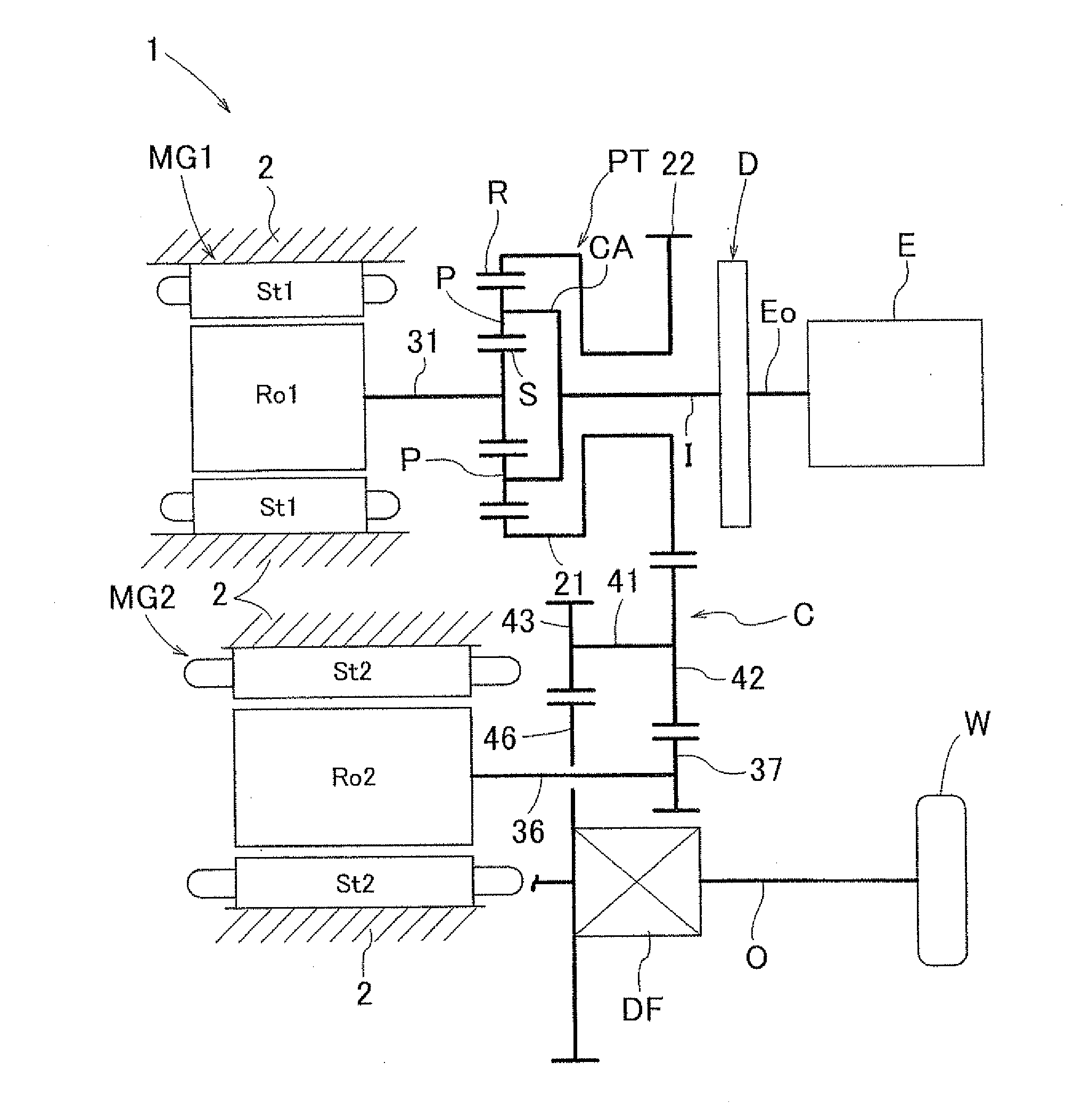
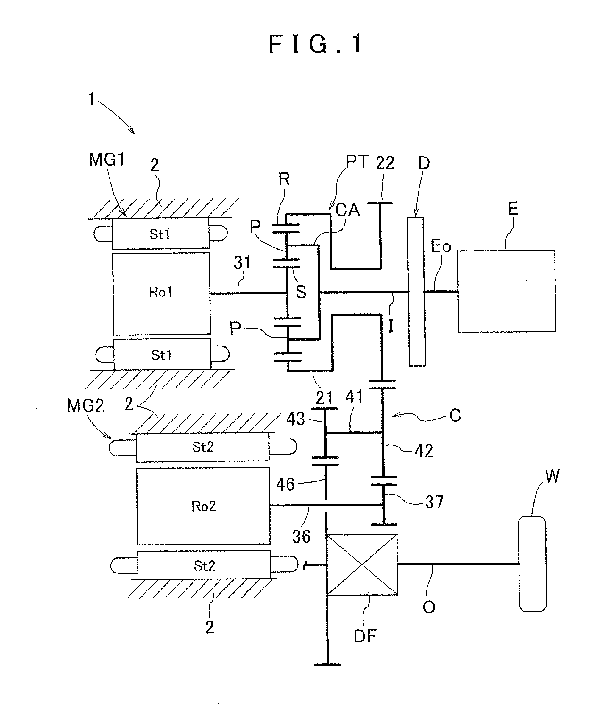
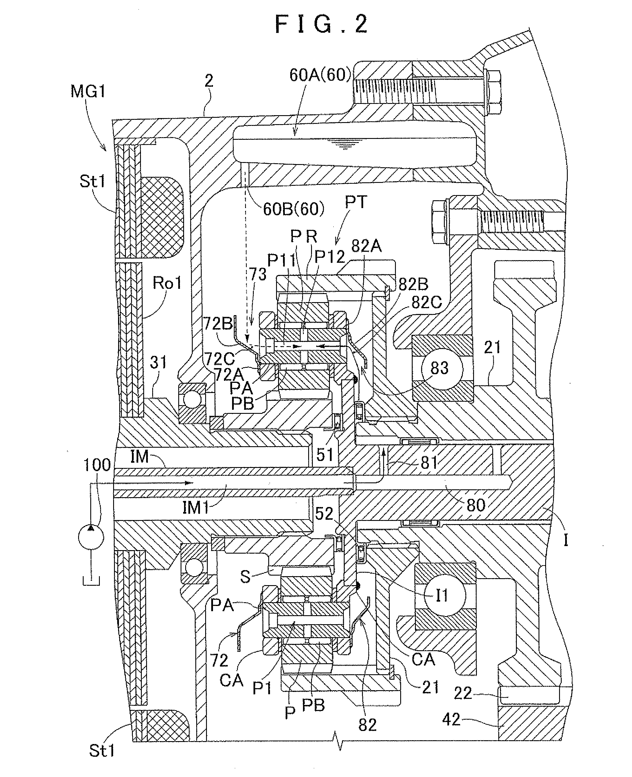
[0038]A vehicle drive apparatus 1 according to the present invention is structured to be capable of supplying a lubricating fluid to pinion bearings which a planetary gear mechanism PT includes even when a pump driven by an engine is in a stopped state. Hereinafter, such a vehicle drive apparatus 1 will be described with reference to the drawings. FIG. 1 illustrates a skeleton diagram of the vehicle drive apparatus 1 according to this embodiment, and FIG. 2 illustrates a cross-sectional view of a substantial part of the vehicle drive apparatus 1 according to this embodiment.

[0039]The vehicle drive apparatus 1 is a drive apparatus for a hybrid vehicle capable of traveling using both an engine E and two rotary electrical machines MG1, MG2 as driving force sources, and is particularly suitable for a plug-in hybrid vehicle which stops the engine E and travels for a long time using the rotary electrical machine MG2 as a motive power source. The vehicle drive appa...

second embodiment

[0078]2. Second Embodiment

[0079]In the description of the first embodiment, the outward receiver 72 includes an attaching portion 72A, an extending portion 72B, and a receiving portion 72C, and the bearing lubricating passages P1 are structured to have a fluid through passage P11 and a fluid communication passage P12. This embodiment is different from the first embodiment in that the outward receiver 72 includes an outer peripheral groove 72D and communication holes 72E, and the bearing lubricating passages P1 are structured to have a fluid communication passage P12, a first bearing lubricating passage P17, and a second bearing lubricating passage P18. Besides the outward receiver 72 and the bearing lubricating passages P1, this embodiment has the same structure as the first embodiment, and thus the outward receiver 72 and the bearing lubricating passages P1 will be described below.

[0080]FIG. 3 illustrates a cross-sectional view of a substantial part of a vehicle drive apparatus 1 a...

third embodiment

[0084]3. Third Embodiment

[0085]In the description of the first embodiment, the outward receiver 72 is attached to the end face in the apparatus axial direction of the carrier CA on the side of the first rotor Ro1, and the inward receiver 82 is attached to the end face in the apparatus axial direction of the carrier CA on the side of the distribution output member 21. This embodiment is different from the first embodiment in that the outward receiver 72 is attached to the end face in the apparatus axial direction of the carrier CA on the side of the distribution output member 21, and the inward receiver 82 is attached to the end face in the apparatus axial direction of the carrier CA on the side of the first rotor Ro1. That is, in this example, the right side in FIG. 5 corresponds to “one side in the apparatus axial direction”, and the left side in FIG. 5 corresponds to “the other side in the apparatus axial direction”. Hereinafter, a vehicle drive apparatus 1 structured thus will be...


PUM


Abstract

A vehicle drive apparatus comprising a planetary gear mechanism having a ring gear drive-coupled to one of an output member drive-coupled to wheels and a rotary electrical machine, a sun gear drive-coupled to the other of the output member and the rotary electrical machine, and a carrier drive-coupled to an engine and rotatably supporting a plurality of pinion gears, the apparatus. The vehicle drive apparatus having an outward receiver comprising a receiving portion opening outward in an apparatus radial direction and being provided on the carrier, the apparatus radial direction being a radial direction of the ring gear; a fluid supply part supplying lubricating fluid to an opening of the receiving portion of the outward receiver; and a bearing lubricating passage which is a route of lubricating fluid connecting the receiving portion of the outward receiver with a pinion bearing of each of the pinion gears.

Description

INCORPORATION BY REFERENCE[0001]The disclosure of Japanese Patent Application No. 2010-168253 filed on Jul. 27, 2010 and Japanese Patent Application No. 2010-059181 filed on Mar. 16, 2010 including the specification, drawings and abstract is incorporated herein by reference in its entirety.BACKGROUND OF THE INVENTION[0002]The present invention relates to a vehicle drive apparatus including a planetary gear mechanism having a ring gear drive-coupled to one of an output member drive-coupled to wheels and a rotary electrical machine, a sun gear drive-coupled to the other of the output member and the rotary electrical machine, and a carrier drive-coupled to an engine and rotatably supporting a plurality of pinion gears.DESCRIPTION OF THE RELATED ART[0003]Conventionally, hybrid vehicles having a rotary electrical machine and an engine are used. In recent years, plug-in hybrid vehicles (hereinafter called “hybrid vehicles” unless it is particularly necessary to distinguish the plug-in hyb...

Claims


Application Information

Patent Timeline
Patent Type & Authority Applications(United States)
IPC IPC(8): B60K6/365F16H3/44F16H57/04
CPCB60K6/365B60K6/445F16H57/0427F16H57/043Y02T10/6239F16H57/0471F16H57/0479F16H2037/0866F16H57/045Y02T10/62
Inventor KOMATSU, TAKUYASADA, NATSUKIATARASHI, TOMOO
Owner AISIN AW CO LTD
Why Eureka
Try Eureka