Method and device for lubricating bearing positions, especially in machine tools or their parts

a technology for lubricating bearing positions and machine tools, which is applied in the direction of shafts, maintenance and safety accessories, turning apparatuses, etc., can solve the problems of affecting functional reliability, affecting the service life of the toolholder, etc., and achieves favorable tribological relationships and high stress.

Active Publication Date: 2009-03-31
ESA EPPINGER
View PDF27 Cites 5 Cited by
  • Summary
  • Abstract
  • Description
  • Claims
  • Application Information

AI Technical Summary

Benefits of technology

[0005]The object of the invention is therefore to increase the functional reliability and lifetime in machines, especially in machine tools and here especially in toolholders having driven, very high-speed spindles.
[0008]According to the invention, in place of the customary lubrication intervals and lifetime lubrication, there is performed a lubricant-mist lubrication of the bearing positions and gear means, such as in toolholder housing, in which lubricant mist, which supplies the bearing positions and gear means with the amount of lubricant required for high stress and also results in very favorable tribological relationships, flows through the housing. Since the lubricant path, from its inlet to its outlet, extends through the entire housing and the lubricant mist consequently flows through the housing, the lubricant mist simultaneously carries off heat and thereby cools the bearing positions and gear means. On the lubricant path, the lubricant mist is under a certain pressure, whereby an overpressure of 1 bar, for example, relative to the atmosphere can be produced. This overpressure in the housing also prevents fine contaminants from the work space, such as coolant or small chip particles, from penetrating the housing, it being possible according to circumstances to “suck” such contaminants into the housing through cleavages in the housing when the temperature relationships and therefore the pressure relationships in the housing change depending on the operation.
[0009]It is known to impinge tool carriers, such as tool turrets and toolholders or spindle units on machine tools, with sealing air, generating a slight overpressure inside the housing relative to the work space and making it more difficult for chips or coolant or lubricant to penetrate. But such an impingement of sealing air causes an extra expense, which is saved in the device according to the invention, because the lubricant mist, which flows through the housing and is under pressure according to the invention, simultaneously creates a sealing effect in the spirit of sealing-air impingement and thereby effects a pneumatic seal against the work space.
[0012]In the depicted application of the invention on a toolholder, which is used in a tool carrier, such as in the form of a tool turret, it is advantageous for the lubricant path to also extend through the tool carrier so that an inlet is provided on the tool carrier or a part associated with the tool carrier. In this manner, it is possible to simultaneously achieve appropriate lubrication, cooling and pneumatic sealing of gear means, bearing positions and the like, including within the tool carrier. If necessary, the lubricant path can be branched in such a manner that the tool carrier is provided with its own outlet, to which its own condensation means are associated.

Problems solved by technology

Due to their confined spatial relationships, such as those prevailing on a turret disk, such toolholders have very limited space and are subject to extreme working conditions, the trend being toward higher and higher spindle speeds (30,000 RPM and more).
These considerations also keep raising the requirements on bearings and gear parts, especially on their lubrication and cooling, while at the same time the question of providing a perfect seal against the conditions prevailing in the work space for the bearing positions and gear parts arranged in the housing keeps gaining in importance, since the penetration of coolant into the housing can rapidly impair functional reliability.
The currently customary lubrication intervals and lifetime lubrication of bearing positions often no longer suffice for these high stresses.
Although there are efforts to relieve the tools engaging the workpiece, the work space and the environment from excessive stresses caused by coolants, cutting oils and the like by means of minimum quantity lubrication, this does not solve the problem of efficient lubrication and cooling and any required housing seal for high-speed tools, such as in toolholders.
Fundamentally similar problems are quite generally appearing to a growing extent in machine tools and their aggregates, which are operating with higher and higher spindle speeds like those required for modern machining operations.
Here too, less and less adequate lubrication and cooling of the bearing positions and gear parts while stresses are increasing is leading to an undesirable decrease in lifetime or to impaired functional reliability.

Method used


Image

  • Method and device for lubricating bearing positions, especially in machine tools or their parts
  • Method and device for lubricating bearing positions, especially in machine tools or their parts
  • Method and device for lubricating bearing positions, especially in machine tools or their parts

Examples


Embodiment Construction

)

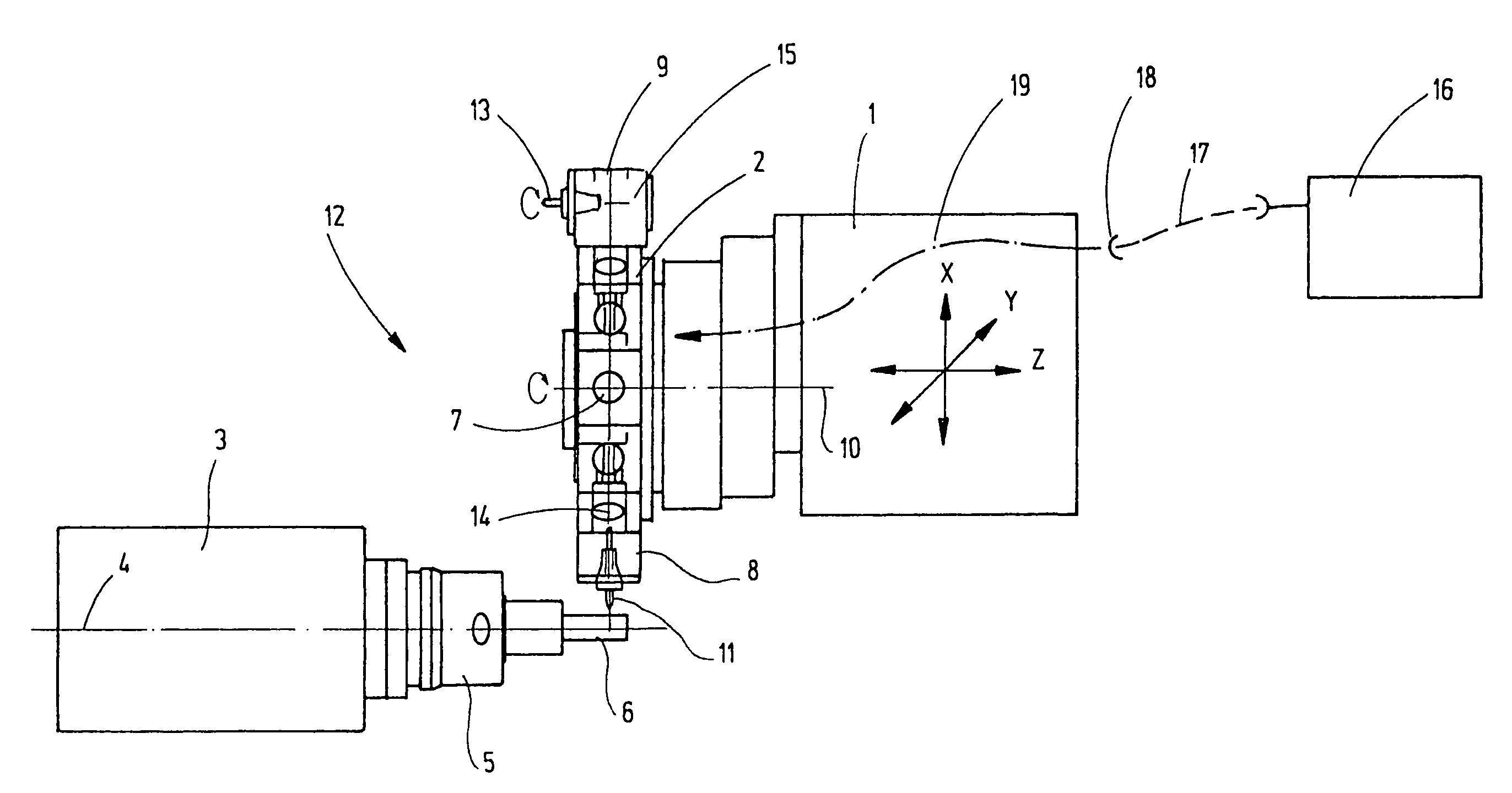
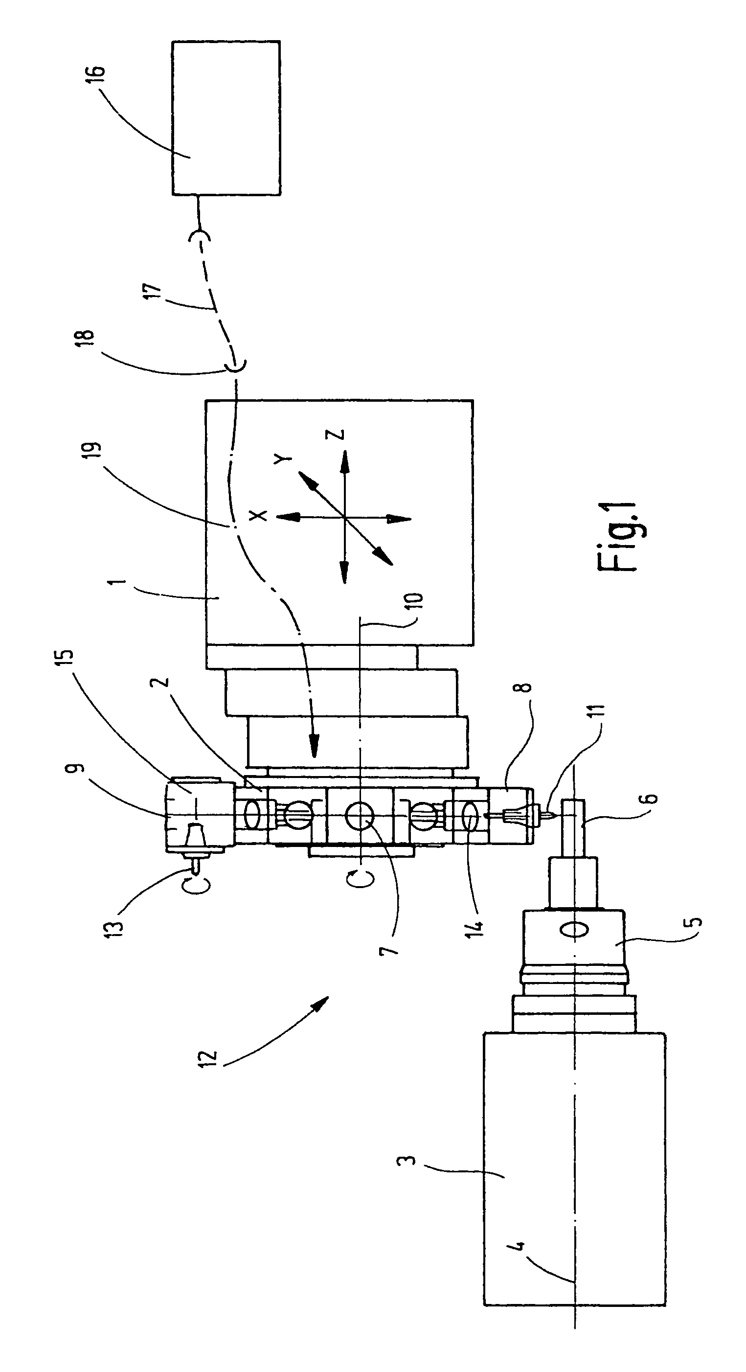
[0020]In the largely schematic representation of a CNC lathe, only the essential parts of the machine are illustrated in FIG. 1. The lathe demonstrates a tool turret 1, which bears, as actual tool carrier, a switchable turret disk 2 that travels horizontally along axes X and Z and vertical to the plane of the drawing and to an associated headstock 3 along axis Y. The headstock 3 is equipped with a chuck 5, which surrounds a rotational axis 4 and clamps a workpiece, indicated by 6.

[0021]Radially aligned insertion bores 7, into each of which a toolholder with its cylindrical clamping shaft can be inserted, are distributed along the perimeter of the turret disk or general tool-carrier disk 2. Of these toolholders, two toolholders 8, 9 are illustrated, toolholder 8 bearing a tool 11 that runs radial to the swiveling axis 10 of the tool-carrier disk 2 and toolholder 9 being equipped with a tool 13 aligned parallel to the turret axis 10. Both tools 11, 13 are driven in a manner yet to be...


PUM

PropertyMeasurementUnit
droplet sizeaaaaaaaaaa
pressureaaaaaaaaaa
diameteraaaaaaaaaa

Abstract

In a device on machines, especially machine tools and their parts, such as tool holders comprising at least one rotating element, which is rotatably mounted at least in one bearing position arranged in a housing, a lubricating device is provided for this bearing position. For this, the bearing position is located in a lubricant path, which extends from an inlet to an outlet in the housing and into which there is fed under pressure a lubricant mist, which flows through the lubricant path up to the outlet. The outlet is connected to condensation means for the residual quantity of lubricant mist reaching the outlet, so that only condensed lubricant escapes to the outside. The lubricant mist flowing through the housing effects lubrication and cooling of the bearing position and at the same time effects a pneumatic seal of the housing to the outside to prevent contaminants from penetrating.

Description

BACKGROUND OF THE INVENTION[0001]The invention relates to a device on machines, especially machine tools, comprising at least one rotating element, which is rotatably mounted in a bearing position arranged in a housing, and a lubricating device for this bearing position that can at least intermittently supply the bearing position with a lubricant. The invention additionally relates to a method for lubricating elements surrounding bearing positions and / or gear means, especially in machines tools or their parts.SUMMARY OF THE INVENTION[0002]For example, toolholders for driven tools on tool carriers, such as tool turrets of CNC-controlled machine tools, are in principle small spindle units adapted to the work space and working conditions. They are used for stationary and rotating tools, the toolholders for rotating tools generally not having their own drive, but being driven by a power source coming from the tool carrier. Due to their confined spatial relationships, such as those preva...

Claims


Application Information

Patent Timeline
Patent Type & Authority Patents(United States)
IPC IPC(8): B23B3/16B23C1/00
CPCB23Q11/123F16C33/6659F16N7/32Y10T409/303976Y10T29/5155F16C2322/39B23Q11/00B23Q11/12
Inventor NEUMEIER, MANFRED
Owner ESA EPPINGER
Why Eureka
Try Eureka