Long-piston hydraulic machines

A technology of hydraulic presses and pistons, applied in the field of hydraulic pump/motor machines, can solve problems such as limitations and achieve the effect of cheap manufacturing

Inactive Publication Date: 2005-10-26
TORVEC INC
View PDF0 Cites 4 Cited by
  • Summary
  • Abstract
  • Description
  • Claims
  • Application Information

AI Technical Summary

Problems solved by technology

While smaller errors can often be used to reduce blowby, the reduction of these errors is limited by the need for adequate lubrication

Method used


Image

  • Long-piston hydraulic machines
  • Long-piston hydraulic machines
  • Long-piston hydraulic machines

Examples


Embodiment Construction

[0024] The operation of hydraulic machines of the type that can be augmented by the present invention is known. Therefore, this operation will not be described in detail.

[0025] hydraulic motor

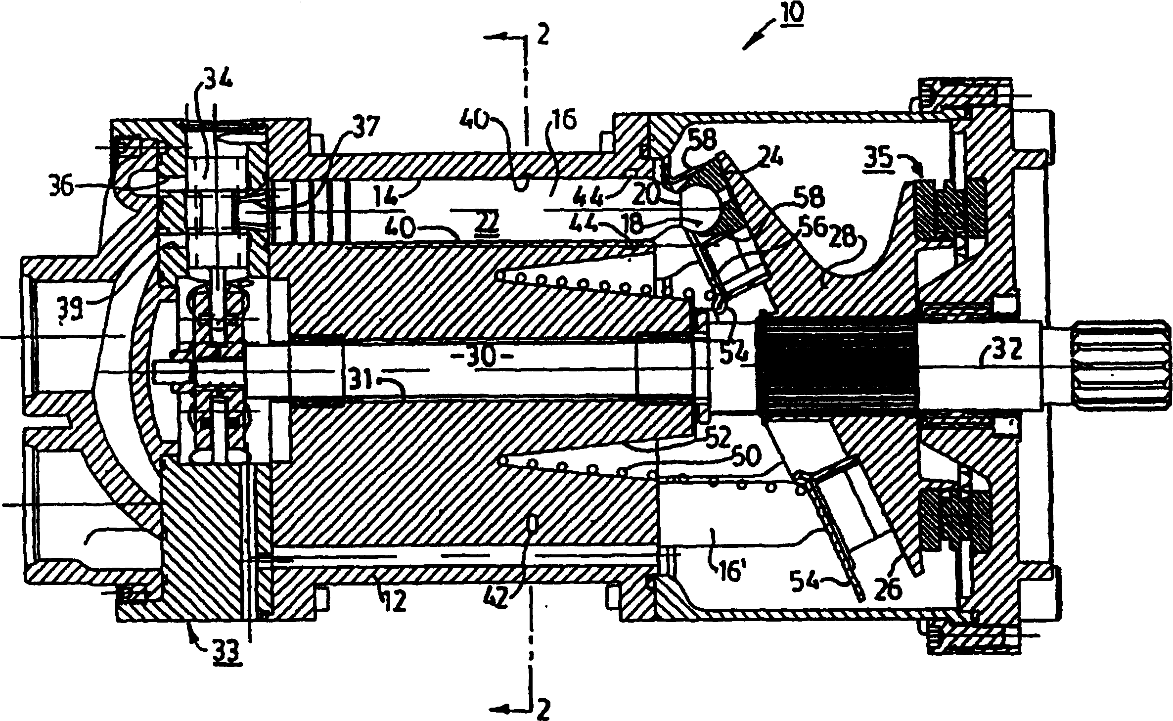
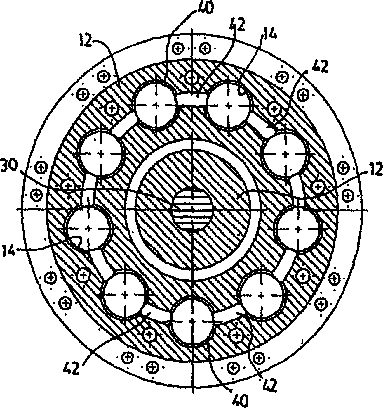
[0026] refer to figure 1 , the hydraulic motor 10 includes a stationary cylinder 12 having a plurality of cylinders 14 (only one shown), wherein a corresponding plurality of mating pistons 16 reciprocates between a retracted position of the piston 16 and an extended position of the piston 16'. Each piston has a spherical head 18 mounted on a neck 20 at one end of an elongated axially cylindrical body portion 22 which, in the preferred embodiment shown, is substantially aligned with each respective cylinder. 14 is the same length.

[0027] Each spherical end 18 fits in a respective shoe sliding on a plane 26 formed on the surface of a rotor 28 co-fixed on the drive element, ie the shaft 30 of the machine. The shaft 30 is supported on bearings in a bore 31 at the center of the cylin...


PUM


Abstract

A smaller, lighter hydraulic pump or motor is provided with pistons, each of which has a body with a length approximately equal to the axial length of a corresponding cylinder in which the piston to-and-froly moves. A plurality of corresponding lubricating grooves which are circumferentially formed and radially traverse the wall of each cylinder are respectively positioned at positions which are always closed by the axial cylindrical body of each corresponding piston during the whole travel. The lubricating grooves are connected with one another to form a continuous lubricating channel totally positioned in the cylinder, and not connected by the input or output channels of fluid but supplemented by the blowby entering from the valve end of each cylinder. A plurality of sealing parts respectively positioned near the opening of each cylinder provide strong sealing and nearly eliminate the blowby coming from the lubricating channel, thus notably increasing the volumetric efficiency. The formed improved lubrication, combined with the only spring biasing holddown component, can use a variable-angle swash cam arrangement, which does not need not only a dogbone part on the outer end of the piston but also an ordinary swinger which can only nutate.

Description

technical field [0001] This invention relates to hydraulic pump / motor machines having elongated pistons reciprocating within cylinders, and more particularly to a method for lubricating these pistons while maintaining contact between the heads of these pistons and the swash plate of said pump / motor system. Background technique [0002] Hydraulic pumps and motors are known and widely used, having reciprocating pistons mounted in respective cylinders formed in the cylinders and arranged circumferentially at a first radial distance around the axis of rotation of the drive element. Many of these pump / motor machines have variable displacement capability; and they are generally of two basic designs: (a) a piston reciprocates within a rotating cylinder against a variably inclined, but otherwise fixed, swash plate Motion or (b) piston reciprocation within a fixed cylinder against a variably tilted and turned swash plate, usually split, consisting of non- Turn (but nutate) the rock...

Claims


Application Information

Patent Timeline
Patent Type & Authority Applications(China)
IPC IPC(8): F04B1/12F04B27/10
CPCF04B1/141F04B27/109F04B1/143F04B1/126F04B27/10F04B27/08
Inventor 弗农·E·格利斯曼基思·E·格利斯曼马修·R·弗罗纳
Owner TORVEC INC
Why Eureka
Try Eureka