Active constrained type cast-in-situ frame beam-column joint system based on retard-bonded prestress technology

A slow-bonded prestressed, beam-column joint technology, applied in protective buildings/shelters, building components, earthquake resistance, etc., can solve the problems of joint hysteresis performance degradation, stiffness degradation, unfavorable construction, etc., to increase construction Effects of burden, improvement of shear resistance, and improvement of bonding performance

Active Publication Date: 2018-03-13
DALIAN UNIV OF TECH
View PDF8 Cites 5 Cited by
  • Summary
  • Abstract
  • Description
  • Claims
  • Application Information

AI Technical Summary

Problems solved by technology

At present, there are two main problems in the design and construction of conventional beam-column joints: first, under repeated loads, the concrete in the beam-column joint area will crack along the direction of the main tensile stress, which will lead to a decrease in the hysteretic performance of the joint, which is manifested as stiffness continued degradation of
At the same time, in order to ensure the rotation capacity of the plastic hinge, the steel bars at the beam end or column end will pass through the joint area and be anchored, resulting in more concentrated steel bars in the joint area, which is not conducive to construction

Method used


Image

  • Active constrained type cast-in-situ frame beam-column joint system based on retard-bonded prestress technology
  • Active constrained type cast-in-situ frame beam-column joint system based on retard-bonded prestress technology
  • Active constrained type cast-in-situ frame beam-column joint system based on retard-bonded prestress technology

Examples


Embodiment Construction

[0020] The specific implementation method of the present invention will be further described below in conjunction with the accompanying drawings and technical solutions.

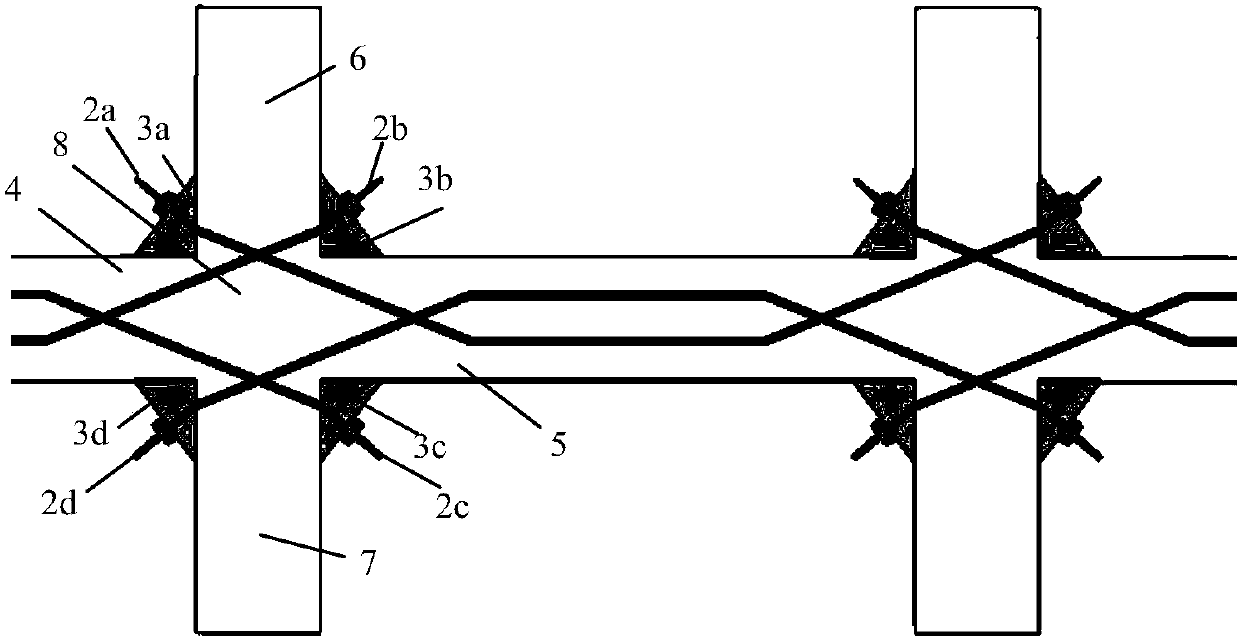
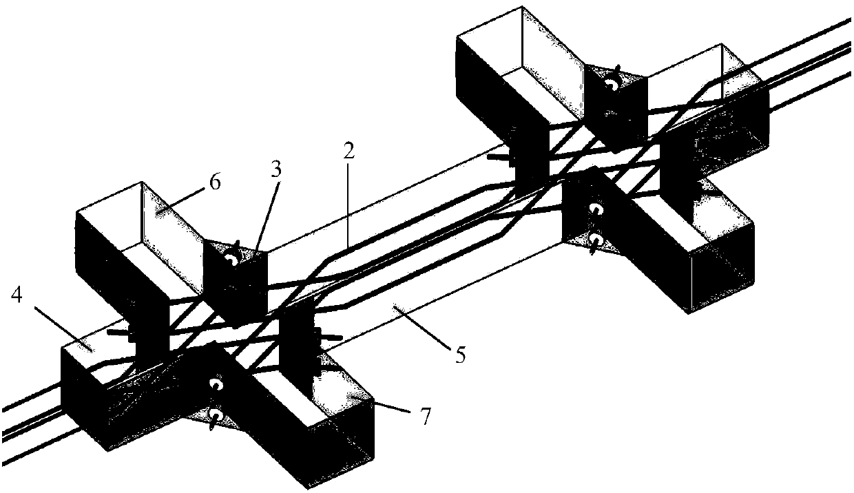
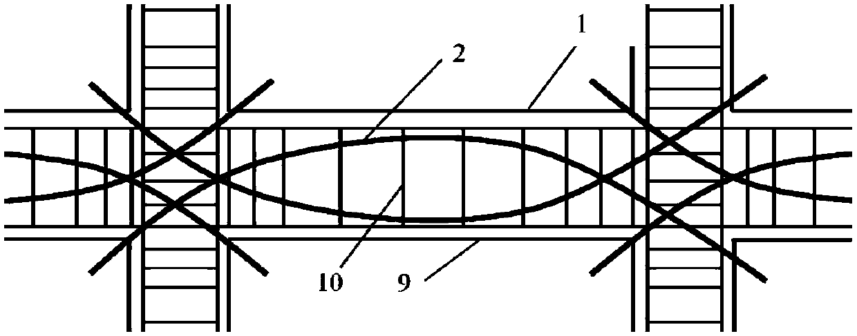
[0021] An active restraint cast-in-place frame beam-column joint system based on slow-bonded prestressing technology, including cast-in-place frame beam-column joints 1, slow-bonded prestressed tendons 2 and wedge anchors 3. The cast-in-place frame beam-column node 1 is a cross-shaped structure, including the left cast-in-place concrete beam 4, the right cast-in-place concrete beam 5, the upper side cast-in-place concrete column 6, the lower side cast-in-place concrete column 7 and the node core Zone 8, the central part of the cross-shaped structure is the node core zone 8.

[0022] The wedge-shaped anchorage 3 is arranged at the joint between the column and the beam end, and its right-angled sides coincide with the surfaces of the beam and the column respectively. The slow bonded prestressed tendons 2 are ...


PUM


Abstract

The invention provides an active constrained type cast-in-situ frame beam-column joint system based on a retard-bonded prestress technology and belongs to the field of civil and structural engineering. The system comprises cast-in-situ frame beam-column joints, retard-bonded prestress bars and wedge-shaped anchorage devices. The cast-in-situ frame beam-column joints are each of a cross structure and comprise left-side cast-in-situ concrete beams, right-side cast-in-situ concrete beams, upper-side cast-in-situ concrete columns, lower-side cast-in-situ concrete columns and joint core areas. Thewedge-shaped anchorage devices are arranged on the connecting portions of the ends of the columns and the beams, and the right-angle sides of the wedge-shaped anchorage devices are matched with the surfaces of the beams and the columns. The retard-bonded prestress bars are in arc shapes and buried in cast-in-situ structures, and the two ends of the retard-bonded prestress bars are connected with the wedge-shaped anchorage devices of the corners of the adjacent beam-column joints. After the retard-bonded prestress bars around the cast-in-situ frame beam-column joints are tensioned, through thewedge-shaped anchorage devices, X-shaped active constraint is provided for the cast-in-situ frame beam-column joints. According to the active constrained type cast-in-situ frame beam-column joint system based on the retard-bonded prestress technology, the seismic performance of the joints is improved, lateral displacement of frame structures is reduced, and the system is more convenient to construct.

Description

technical field [0001] The invention belongs to the field of civil engineering and structural engineering, and relates to an active restraint type cast-in-place frame beam-column joint system, in which the active restraint is mainly realized through slow bond prestressing technology. Background technique [0002] Beam-column joints are key components in reinforced concrete cast-in-place frame structures. Under the action of lateral loads such as earthquake or wind, the joints will transmit the bending moment and shear force between the beam and the column, and allow the plastic hinge at the end of the beam to consume energy, so as to protect the main structure from collapsing under large lateral displacement. Therefore, the beam-column joint needs to have a strong shear bearing capacity to prevent it from shear failure before the beam end. At present, there are two main problems in the design and construction of conventional beam-column joints: first, under repeated loads, ...

Claims


Application Information

Patent Timeline
Patent Type & Authority Applications(China)
IPC IPC(8): E04B1/21E04B1/22E04B1/58E04B1/98E04H9/02
CPCE04B1/215E04B1/22E04H9/021
Inventor 张学王子儒吴智敏欧进萍
Owner DALIAN UNIV OF TECH
Why Eureka
Try Eureka