Mark detection method using printing apparatus and printing apparatus

a printing apparatus and mark detection technology, applied in the direction of instruments, thin material handling, visual presentation, etc., can solve the problems of difficulty in detecting eye marks by the mark sensor, increased printing apparatus cost, and inability of the mark sensor to follow eye marks, etc., to achieve the effect of detecting eye marks stably

Inactive Publication Date: 2016-09-22
SEIKO EPSON CORP
View PDF2 Cites 5 Cited by
  • Summary
  • Abstract
  • Description
  • Claims
  • Application Information

AI Technical Summary

Benefits of technology

[0010]The moving section compensates for the location of the mark sensor on the basis of the detection result from the web edge sensor, thereby keeping the mark sensor at a fixed location with respect to the edge of the web. Consequently, the mark sensor can stably detect marks (eye marks) formed on the web.
[0012]When the web is transported in the forward direction, the steering section corrects the location of the web, on the basis of the detection result from the web edge sensor. This correction reduces the shift of the web in the direction intersecting the transport direction, or the lateral displacement of the web.
[0014]When the web is transported in the reverse direction, the moving section compensates for the location of the mark sensor, on the basis of the detection result from the web edge sensor. The mark sensor thereby can stably detect marks (eye marks) formed on the web. Moreover, the detection result from the web edge sensor is shared by the steering section and the moving section to correct the location of the web and compensate for the location of the mark sensor, respectively. This sharing manner can limit an increase in the cost of the printing apparatus.
[0016]By positioning the steering section upstream of a printing section in the transport path of the web, the lateral displacement of the web in the printing section is reduced so that images can be formed at predetermined printing locations.
[0022]The mark sensor detects marks while its location with respect to the edge of the web is compensated for on the basis of the detection result from the web edge sensor which indicates the location of the edge of the web. More specifically, the mark sensor detects marks while its location is compensated for so that the mark sensor is kept at a fixed location with respect to the edge of the web. Therefore, the mark sensor can detect the marks stably.

Problems solved by technology

Disadvantageously, using a high-precision detection sensor may lead to an increase in the cost of the printing apparatus.
This may make it difficult for the mark sensor to follow the eye marks.
If a web is greatly displaced in its width direction, for example at the start of the transport, the mark sensor may fail to detect eye marks.
In short, the printing apparatus has trouble detecting the eye marks stably due to adhesion of foreign objects to the eye marks, the displacement of the web at the start of the transport, and the like.

Method used


Image

  • Mark detection method using printing apparatus and printing apparatus
  • Mark detection method using printing apparatus and printing apparatus
  • Mark detection method using printing apparatus and printing apparatus

Examples


first embodiment

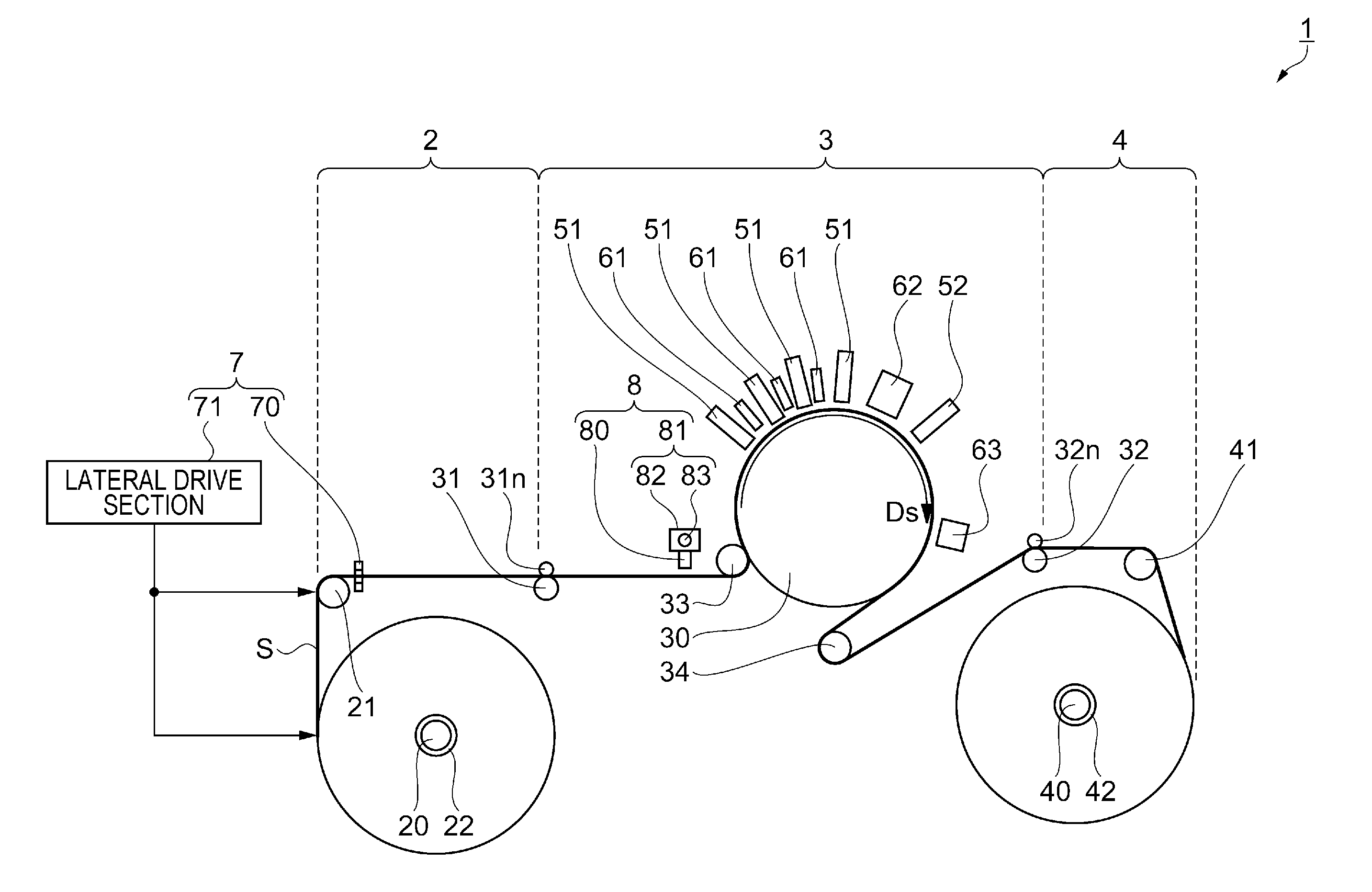
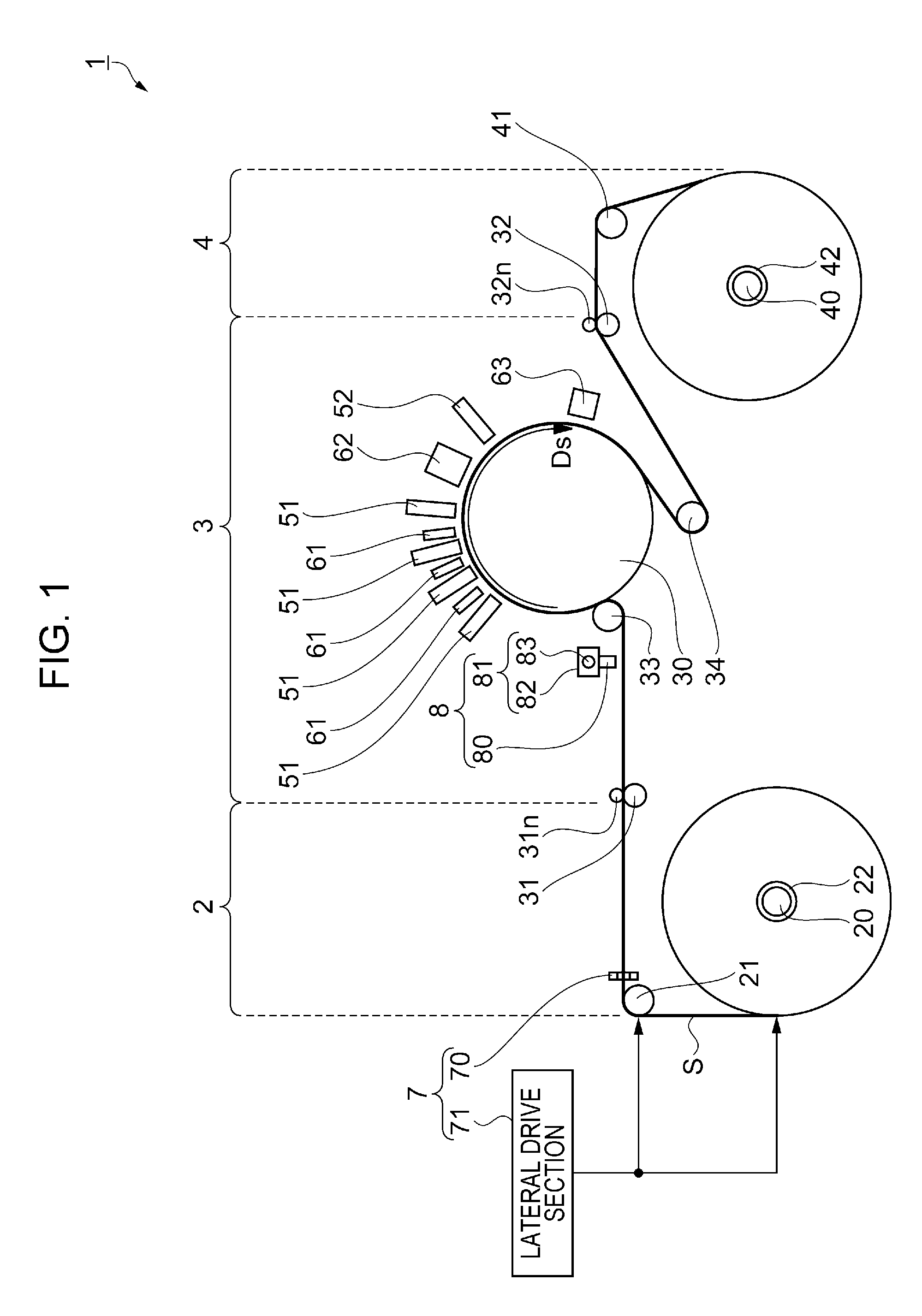
[0030]FIG. 1 is a schematic view illustrating a configuration of a printer according to a first embodiment of the invention.

Outline of Printer

[0031]First, a description will be given of an outline of a printer 1 with reference to FIG. 1. The printer 1 is an example of a “printing apparatus” herein.

[0032]As illustrated in FIG. 1, the printer 1 includes a feeding axis 20 and a winding axis 40. A sheet S (web) is wound in a roll shape around both the feeding axis 20 and the winding axis 40 and stretched therebetween along a transport path. While the sheet S is being transported in a transport direction Ds from the feeding axis 20 to the winding axis 40, images are recorded on the sheet S. Types of sheets S are broadly divided into a paper-based sheet and a film-based sheet. Concrete examples of a paper-based sheet include a high-quality paper sheet, a cast paper sheet, an art paper sheet, and a coated paper sheet; concrete examples of a film-based sheet include a synthetic sheet, a PET...

second embodiment

[0097]FIG. 5 is a schematic view illustrating a configuration of a printer according to a second embodiment of the invention. A printer 10 according to the second embodiment differs from the printer 1 according to the first embodiment in including two edge sensors; edge sensors 70 and 70a. With reference to FIG. 5, the printer 10 according to the second embodiment will be described below mainly regarding differences from the printer 1. Constituent elements that are the same as in the first embodiment are denoted by the same reference characters and will not be described.

[0098]As illustrated in FIG. 5, the edge sensor 70 in the printer 10 is disposed between a driven roller 21 and a front drive roller 31, whereas the edge sensor 70a therein is disposed between the front drive roller 31 and a mark detecting section 8. The edge sensors 70 and 70a have the same configuration and each obtain information regarding the location of an edge of a sheet S in a width direction Dw by detecting t...


PUM


Abstract

A printing apparatus includes a mark sensor, a moving section, a web edge sensor, and a printer control section. The moving section can move the mark sensor in a direction intersecting a transport direction of a sheet, or in a width direction. The web edge sensor can detect a location of an edge of the sheet. The printer control section controls the moving section to compensate for a location of the mark sensor, on the basis of a detection result from the web edge sensor which indicates the location of the edge of the sheet.

Description

BACKGROUND[0001]1. Technical Field[0002]The present invention relates to a mark detection method using a printing apparatus and a printing apparatus employing the mark detection method.[0003]2. Related Art[0004]Some image forming apparatuses (printing apparatuses) known in the art feed a paper sheet (web) disposed in a roll shape to a printing section and form (record) images on this paper sheet. Such printing apparatuses use positioning marks (eye marks) formed on a paper sheet to adjust locations at which images are to be printed (e.g., JP-A-2010-228168).[0005]In an exemplary printing apparatus as described in JP-A-2010-228168, when a web is displaced in its width direction during the transport, the detecting location of a mark sensor follows this web, thus preventing the mark sensor from failing to detect eye marks on the web. More specifically, the printing apparatus locates the centers of an eye mark and a blank area formed in the eye mark in a transport direction of the web on...

Claims


Application Information

Patent Timeline
Patent Type & Authority Applications(United States)
IPC IPC(8): B65H23/02G06K15/02B65H20/02G06K15/00
CPCB65H23/0216B65H20/02G06K15/022G06K15/4025B65H23/038B65H2511/23B65H2511/512B65H2553/30B65H2553/412B65H2601/2531B65H2220/01B65H2220/02B65H2553/81B65H2553/83B65H23/0204B65H23/032
Inventor YAMASHITA, TAKAHIROSHIIYA, TOMOYUKI
Owner SEIKO EPSON CORP
Why Eureka
Try Eureka