Stepping motor drive and stepping motor driving method

a technology of stepping motor and stepping motor, which is applied in the direction of motor/generator/converter stopper, electronic commutator, dynamo-electric converter control, etc., can solve the problems of high-impedance output detection, rotor is likely to lose synchronization, and detection requires a relatively long period of high-impedance output, so as to reduce distortion, stop the determination of a rotor, and suppress the distortion of an ener

Inactive Publication Date: 2009-03-12
PANASONIC CORP
View PDF10 Cites 26 Cited by
  • Summary
  • Abstract
  • Description
  • Claims
  • Application Information

AI Technical Summary

Benefits of technology

[0008]The present invention can suppress the distortions of an energization waveform of a stepping motor and enable the stop determination of a rotor. By reducing

Problems solved by technology

Further, in order to detect a change of current and voltage of induced power on a coil to be detected in the prior art, sufficient time is necessary for the discharge of applied current and a sequence of repeating detection several times, and an exciting method is limited to full-step driving, half-step driving, and so on.
Although a microstep method is available, detection requires a high-impedance outp

Method used


Image

  • Stepping motor drive and stepping motor driving method
  • Stepping motor drive and stepping motor driving method
  • Stepping motor drive and stepping motor driving method

Examples


Embodiment Construction

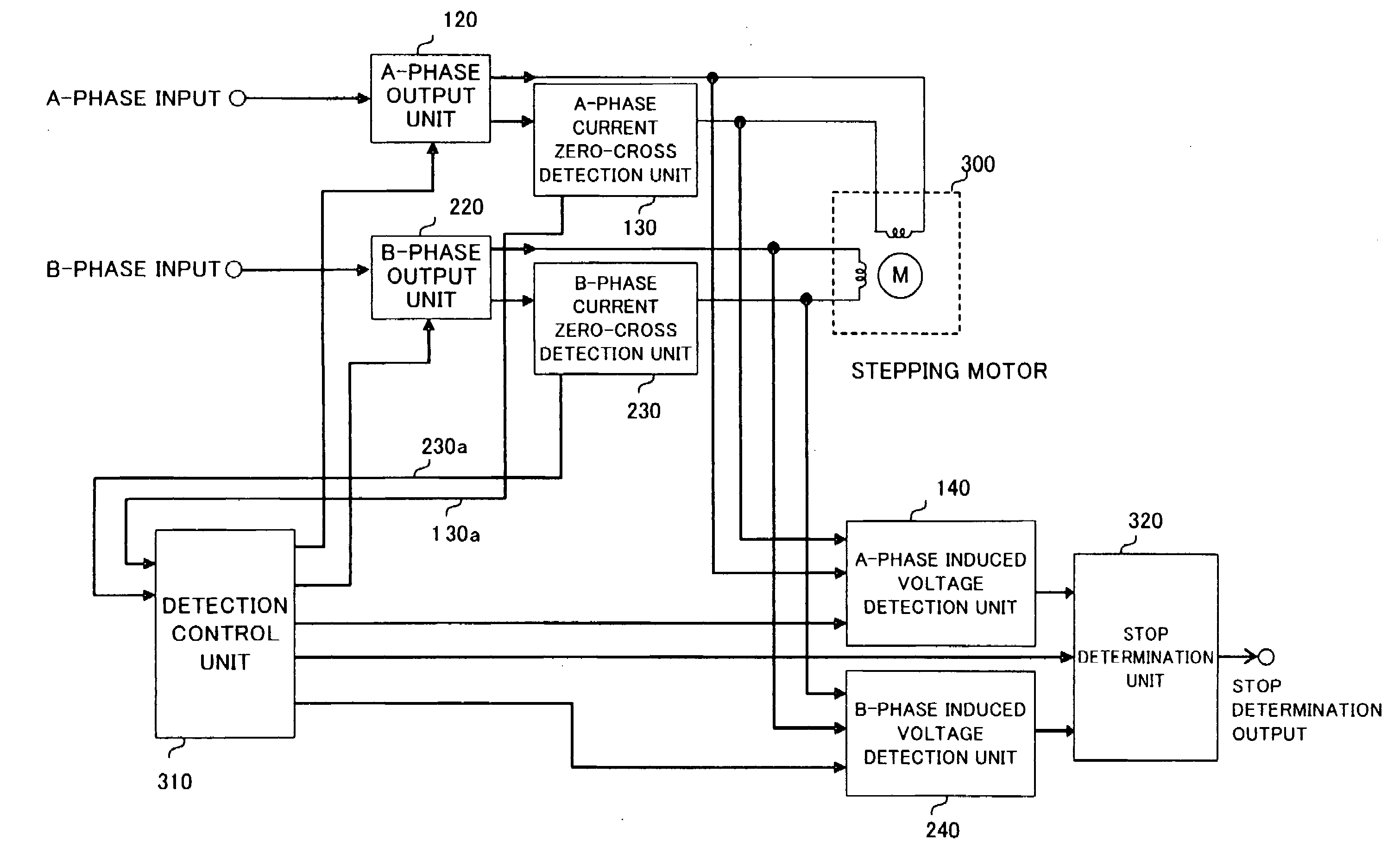
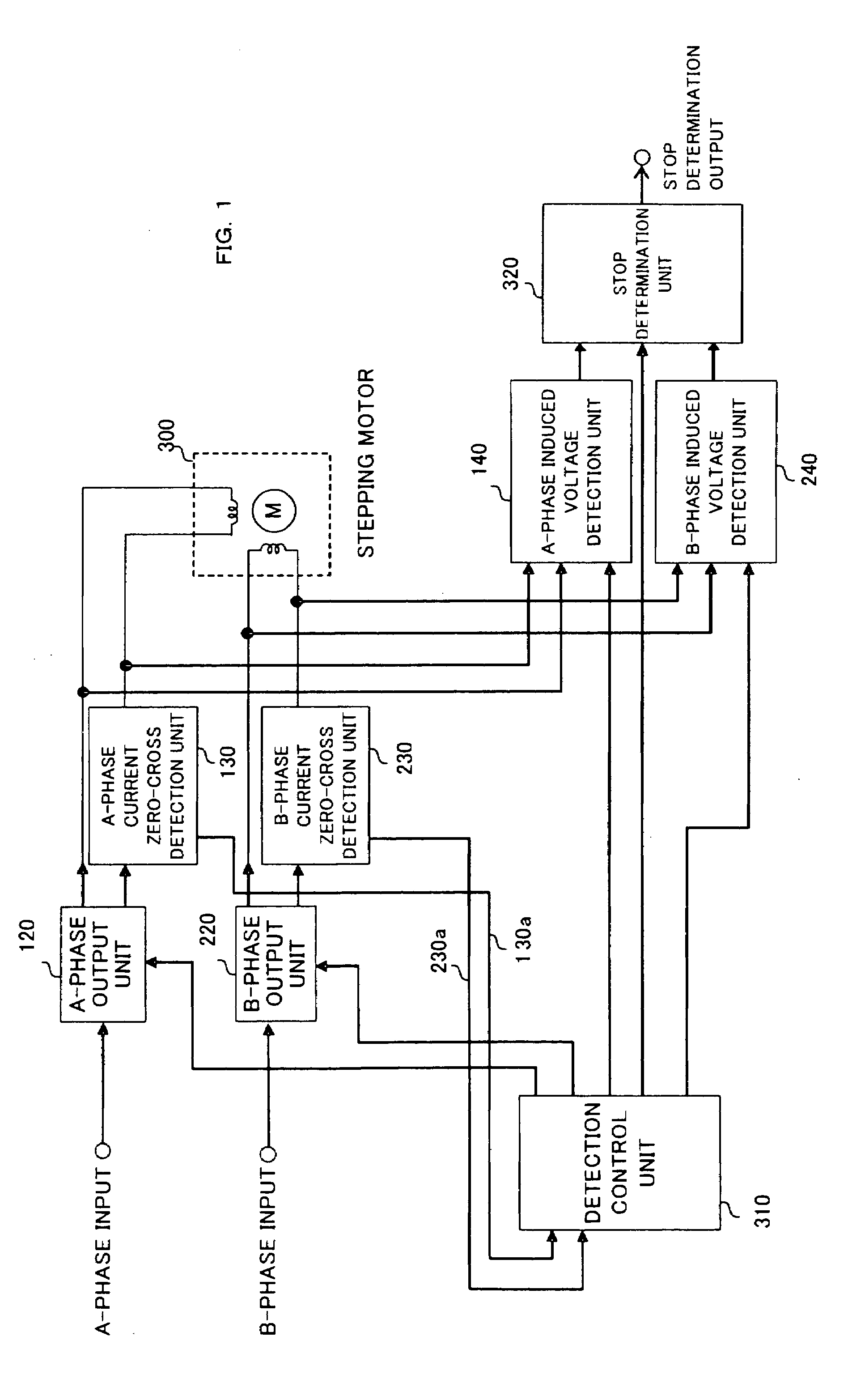
[0023]FIG. 1 is an explanatory drawing showing the embodiment of claim 1 and 13. In FIG. 1, reference numeral 300 denotes a two-phase bipolar stepping motor. An A-phase input signal and a B-phase input signal are fed with an analog signal having one of a sinusoidal wave and a triangular wave with a phase shift of 90° and digital information. In an A-phase output unit (120) and a B-phase output unit (220), the power transistors of one of the output units are driven so as to output a voltage or current obtained by multiplying the values of the A-phase input signal and the B-phase input signal by an optionally set gain.

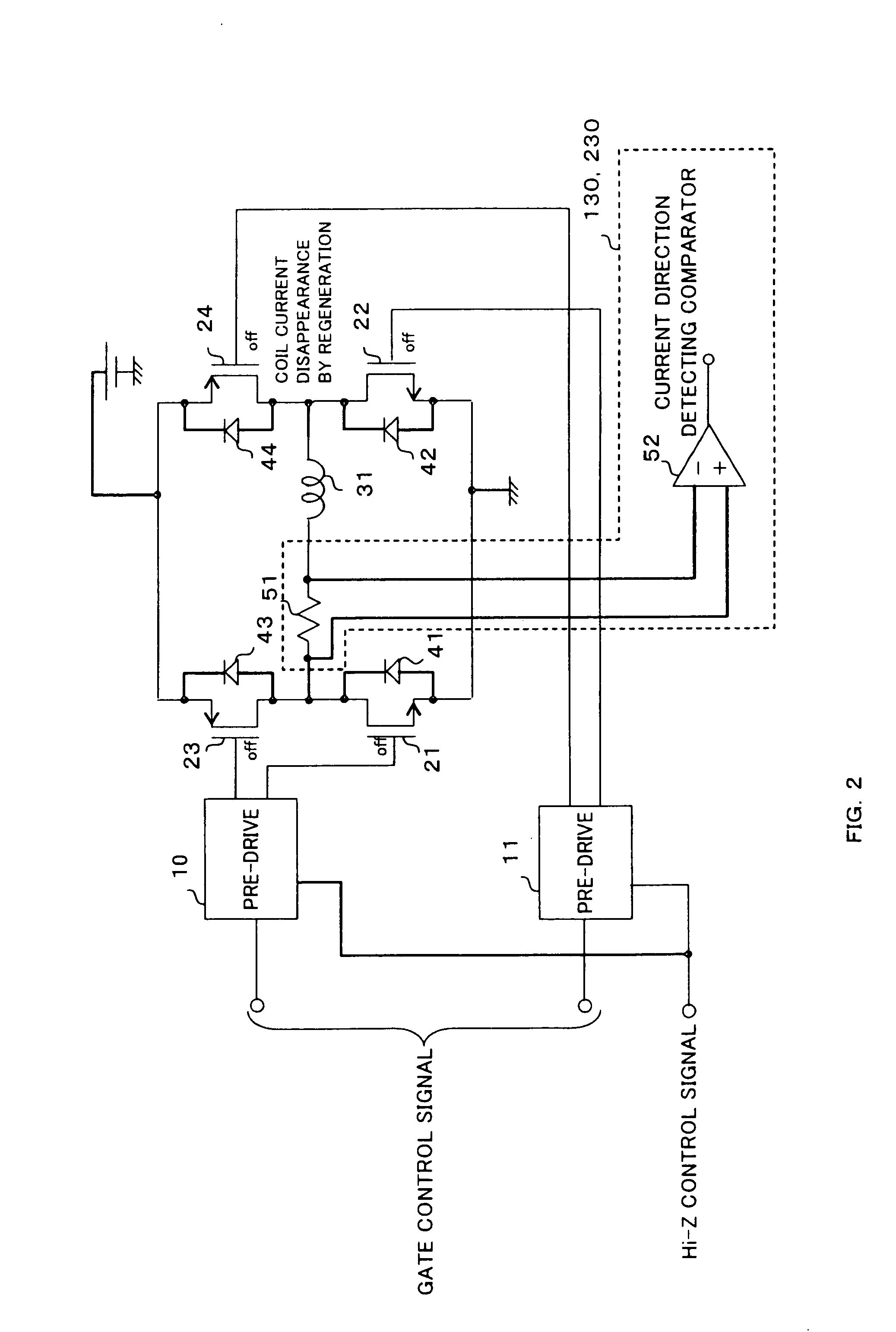
[0024]FIG. 2 shows an example of the configuration of the driven power transistor. FIG. 2 shows an H-bridge configuration for PWM driving. Diodes (41, 42, 43, 44) for regeneration are provided on a power supply and the ground from an output terminal connected to a motor coil (31). Power transistors (21, 22, 23, 24) are driven through pre-drives (10, 11). The power transi...


PUM


Abstract

In a drive of a stepping motor, an electromotive force is generated on the coil of a motor with a sinusoidal wave having the same period as an energization period by smoothly rotating a rotor with microstep driving, and an induced power is stably detected by detecting the electromotive force at the zero cross of driving current. The detection around the current zero cross makes it possible to shorten a detection section, form a driving waveform with few distortions, and perform driving with a driving waveform as in an ordinary micro step. Thus a circuit is provided which is aimed at reducing noise, vibrations, and loss of synchronization, and increasing current consumption efficiency in the determination of stop.

Description

FIELD OF THE INVENTION[0001]The present invention relates to a stepping motor drive and a stepping motor driving method, and particularly relates to a stepping motor drive and a stepping motor driving method which determine whether an optical pickup is stopped or not in an optical disk device.BACKGROUND OF THE INVENTION[0002]Conventionally, before reading or writing data in an optical disk device, it is necessary to read disk information on the innermost end of a disk after power is turned on. However, an optical pickup is not always placed on a predetermined point because of disturbance. Thus the optical pickup is moved to one of the outermost end and the innermost end of the disk to adjust the offset of the position of the optical pickup, and then a reading sequence is started. In this movement to one of the outermost end and the innermost end, an optical sensor and a contact switch have been used to detect arrival at a destination. However, these components are more expensive tha...

Claims


Application Information

Patent Timeline
IPC IPC(8): H02P6/18H02P8/00H02P8/22H02P8/38
CPCH02P8/34H02P8/22Y02P80/10
Inventor ARISAWA, DAIJIRO
Owner PANASONIC CORP
Why Eureka
Try Eureka