Intervertebral implants and graft delivery systems and methods

a technology of intervertebral implants and grafts, applied in the field of spinal implants, can solve the problems of degeneration or other damage of intervertebral discs, and achieve the effect of reducing the likelihood of grafting material migration

Active Publication Date: 2011-09-22
SPINE HLDG LLC
View PDF99 Cites 214 Cited by
  • Summary
  • Abstract
  • Description
  • Claims
  • Application Information

AI Technical Summary

Benefits of technology

[0007]According to some embodiments, excess graft material delivered into the at least one internal chamber through the access port is configured to exit the implant through one or more openings of the anterior wall. In one embodiment, the access port is threaded, so that a delivery tool comprising a corresponding thread pattern can be selectively attached and detached to the spinal implant. In some embodiments, the implant comprises one or more recesses and / or other features configured to mate with corresponding flanges or other protruding members of an implant delivery tool. In one embodiment, each of the first and second lateral walls is configured to generally align with peripheral bearing areas of the adjacent vertebral members. In other embodiments, the teeth along the top and / or bottom surfaces of the implant are configured to slant toward a lateral center of the implant. In some embodiments, the slanted teeth help retain the implant within the target intervertebral space after implantation and / or help reduce the likelihood the migration of grafting materials out of the at least one internal chamber of the implant along the top and bottom surfaces of the implant.

Problems solved by technology

Intervertebral discs can degenerate or otherwise become damaged over time.

Method used


Image

  • Intervertebral implants and graft delivery systems and methods
  • Intervertebral implants and graft delivery systems and methods
  • Intervertebral implants and graft delivery systems and methods

Examples


Embodiment Construction

[0050]A variety of embodiments and examples described herein illustrate various configurations that may be employed to achieve desired improvements. The particular embodiments and examples are only illustrative and not intended in any way to restrict the general nature of the inventions presented and the various aspects and features of and relating to these inventions.

Spinal Implant

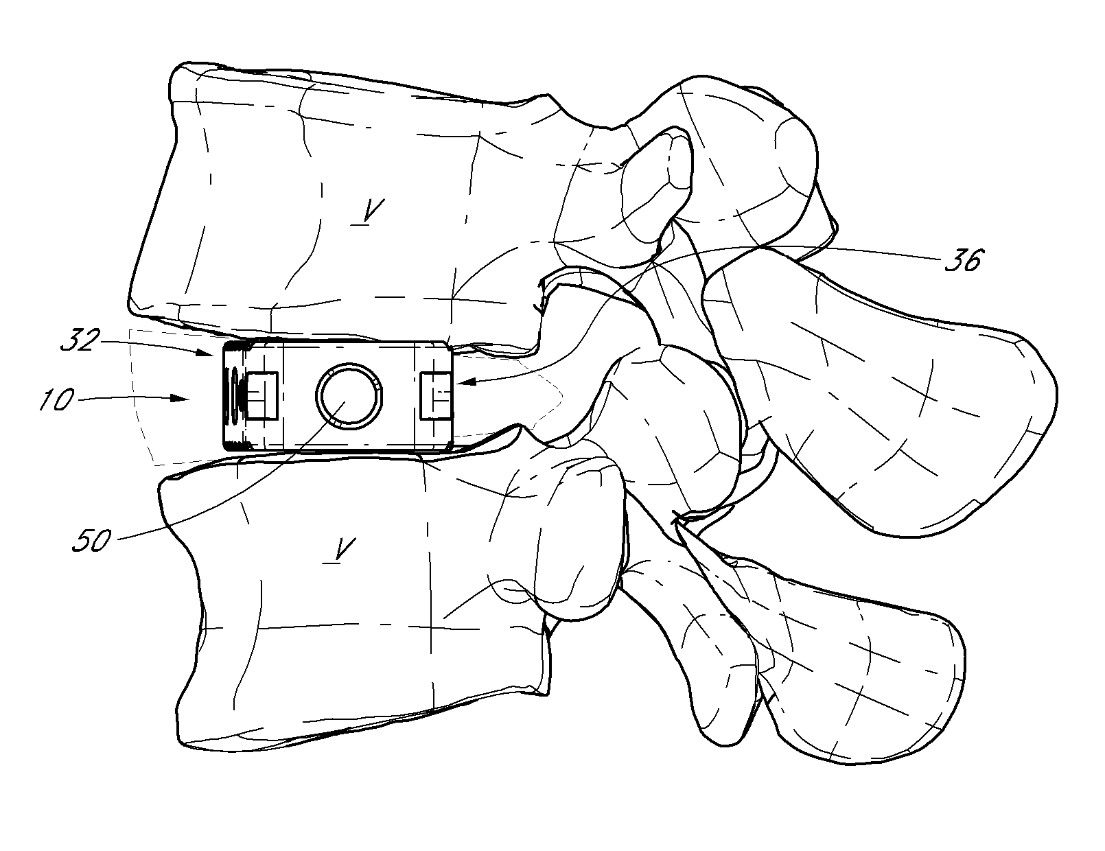
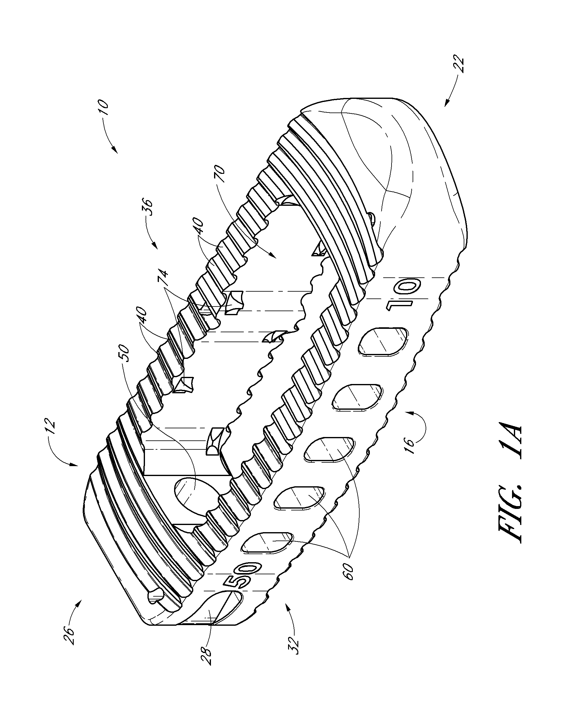
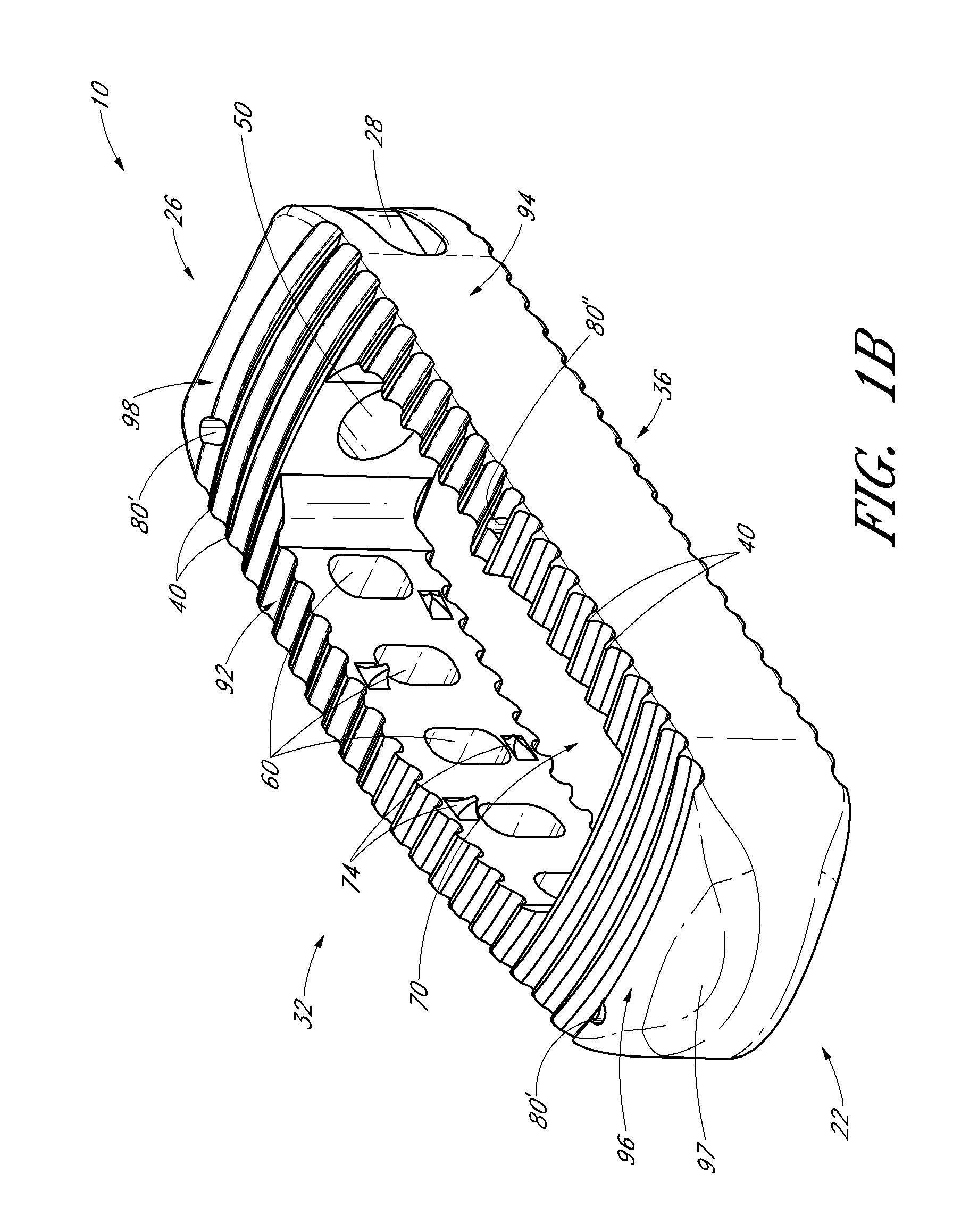
[0051]FIG. 1 illustrates one embodiment of a spinal implant 10 configured for placement between adjacent vertebrae of a patient. According to certain arrangements, the implant 10 is sized, shaped and otherwise adapted for placement with an intervertebral space along the lumbar region of spine. Alternatively, however, the implants and / or the methods disclosed herein can be modified for placement in any other portion of the spine, such as, for example, the thoracic or cervical region. In any of the embodiments disclosed herein, the implant can be inserted into a target intervertebral space using a lateral d...


PUM


Abstract

According to some embodiments, a method for promoting spinal fusion using a spinal implant comprises providing a spinal implant, wherein the spinal implant comprises an anterior wall, a posterior wall and two lateral walls configured to extend between the anterior wall and the posterior wall. In some embodiments, the spinal implant further comprises at least one internal chamber generally positioned between the anterior wall, the posterior wall and the two lateral walls, wherein the internal chamber being is adapted to receive at least one graft and/or other fill material. In some arrangements, the anterior wall of the spinal implant comprises at least one opening or hole that places the internal chamber in fluid communication with an exterior area or portion of the spinal implant. In one embodiment, at least one of the two lateral walls comprises an access port. The method additionally includes positioning the spinal implant between two adjacent vertebrae of a patient and directing at least one graft and/or other fill material into the internal chamber of the spinal implant through the access port. In some embodiments, at least a portion of the graft and/or other fill material delivered into the internal chamber is configured to exit through the one or more of the openings of the anterior wall.

Description

PRIORITY DATA[0001]This application claims the priority benefit under 35 U.S.C. §119(e) of U.S. Provisional Application No. 61 / 314,509, filed Mar. 16, 2010, and U.S. Provisional Application No. 61 / 389,671, filed Oct. 4, 2010, the entire contents of both of which are hereby incorporated by reference herein.BACKGROUND[0002]1. Field[0003]This application generally relates to spinal fusion, and more specifically, to spinal implants and related systems, tools and methods.[0004]2. Description of the Related Art[0005]Intervertebral discs can degenerate or otherwise become damaged over time. In some instances, an intervertebral implant can be positioned within a space previously occupied by a disc. Such implants can help maintain a desired spacing between adjacent vertebrae and / or promote fusion between adjacent vertebrae. The use of bone graft and / or other materials within spinal implants can facilitate the fusion of adjacent vertebral bodies. Accordingly, a need exists for an improved int...

Claims


Application Information

Patent Timeline
Patent Type & Authority Applications(United States)
IPC IPC(8): A61F2/44
CPCA61F2/442A61F2/4465A61F2/4611A61F2002/2817A61F2002/2835A61F2002/3008A61F2310/00011A61F2002/4475A61F2002/4628A61F2002/4629A61F2002/4631A61F2002/464A61F2002/30904A61F2/4637A61F2002/30593A61F2/4455A61F2/447A61F2/46A61F2/4601A61F2002/30261A61F2002/30281A61F2002/30754
Inventor LYNN, JIM R.NELSON, RUSSELL W.
Owner SPINE HLDG LLC
Why Eureka
Try Eureka