Laminated core punching apparatus

a core punching and laminating technology, applied in the field of laminated core punching apparatus, can solve the problems of rotor punching, accumulator that is required when two, and the running condition of strip-form steel plate is more likely to become unstable, so as to achieve large effect, improve line speed, and prevent loop from inverting

Active Publication Date: 2011-09-29
NORITSU KIKAI SEISAKUSHO
View PDF6 Cites 32 Cited by
  • Summary
  • Abstract
  • Description
  • Claims
  • Application Information

AI Technical Summary

Benefits of technology

[0018]A further point to be noted is that the loop guide portion is provided above the intermediate loop portion. As described above, the loop guide portion is disposed to be capable of ascending and descending. Therefore, the loop guide portion can be set in an appropriate position even when a loop height varies in accordance with the size of the punched rotor core piece and stator core piece. Further, by providing the loop guide portion, the shape of the loop in the intermediate loop portion can be stabilized, and therefore the loop can be prevented from inverting even when the punching speed of the rotor-punching press machine and the stator-punching press machine, or in other words a line speed, is increased beyond a conventional speed. As a result, an operation can be performed with stability.
[0019]The intermediate loop portion is formed such that in a natural condition, the strip-form steel plate hangs down in a loop shape. When a feed speed of the strip-form steel plate is comparatively low, the loop remains in this natural condition without problems. If the feed speed is increased, however, vibration generated in the strip-form steel plate when the strip-form steel plate is started and stopped in accordance with the p

Problems solved by technology

Moreover, when the speed of the strip-form steel plate passing through the accumulator and at the front and rear thereof is increased, a running condition of the strip-form steel plate is more likely to become unstable.
However, although the method proposed in Japanese Patent Application Publication JP-A-S58-108948 is effect

Method used


Image

  • Laminated core punching apparatus
  • Laminated core punching apparatus
  • Laminated core punching apparatus

Examples


first embodiment

[0037]A laminated core punching apparatus according to an embodiment of the present invention will now be described using FIGS. 1 to 11.

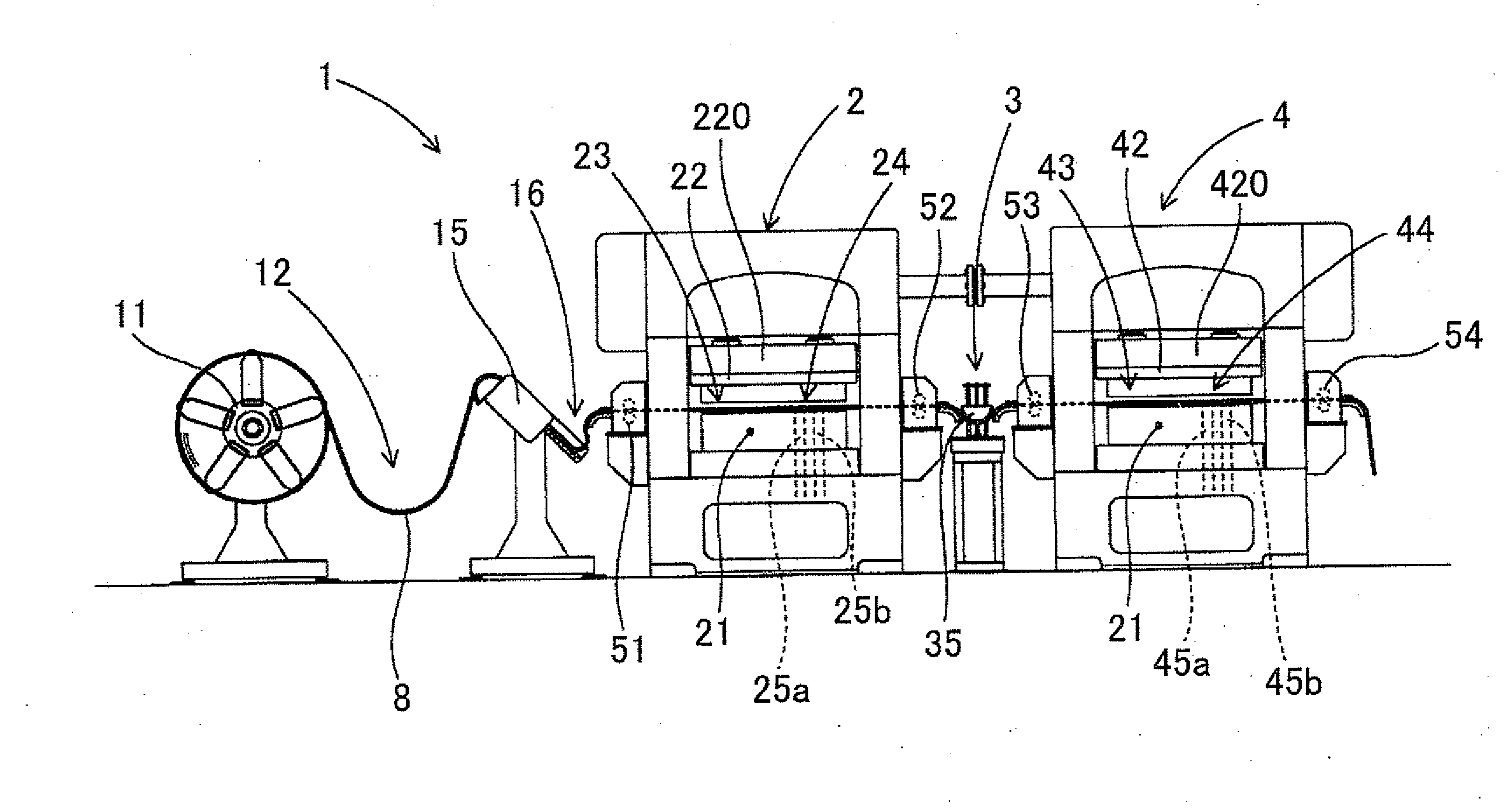
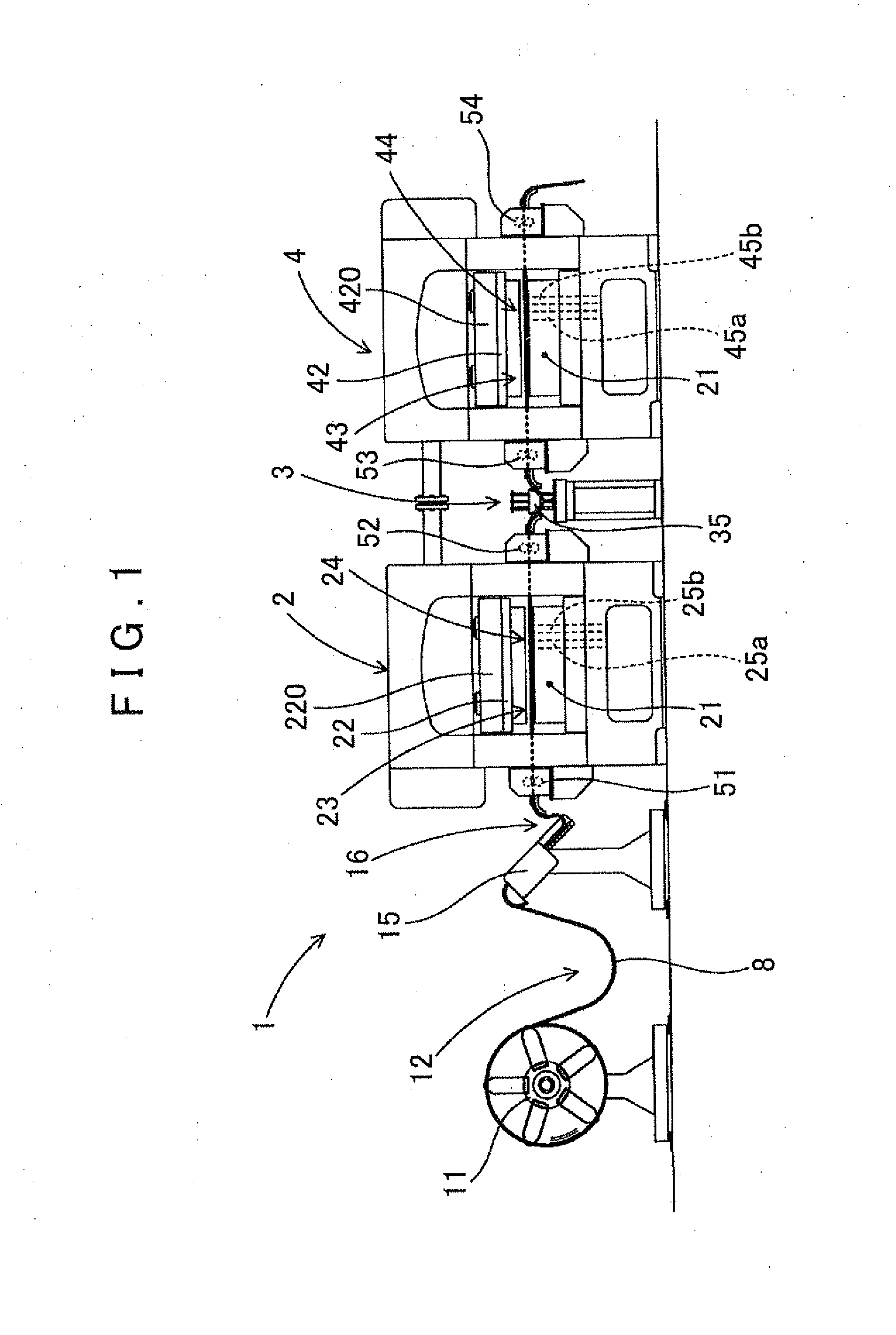
[0038]As shown in FIG. 1, a laminated core punching apparatus 1 according to this embodiment includes an uncoiler 11 for unwinding a strip-form steel plate 8 for an iron core that is wound into a coil shape and set thereon, a rotor-punching press machine 2 for punching out a rotor core piece 81 (FIG. 3) from the strip-form steel plate 8 and laminating the punched rotor core piece 81, and a stator-punching press machine 4 for punching out a stator core piece 82 (FIG. 4) from the strip-form steel plate 8 following punching of the rotor core piece 81 and laminating the punched stator core piece 82.

[0039]The rotor-punching press machine 2 includes a molding die 23 that performs partial punching gradually to approach the shape of the rotor core piece 81, a punching die 24 for punching out the rotor core piece 81 from the strip-form steel plate 8, and two...


PUM

PropertyMeasurementUnit
Diameteraaaaaaaaaa
Diameteraaaaaaaaaa

Abstract

A laminated core punching apparatus, configured such that a stator-punching press machine that has a molding die performing a partial punching gradually approaches the shape of the stator core piece. There is a punching die to punching out the stator core piece from a strip-form steel plate, and two stator lamination stations. A rotor-punching press machine and a stator-punching press machine are constructed to operate synchronously. An intermediate loop portion capable of causing a strip-form steel plate to hang down in a loop is provided in order to adjust a length of the strip-form steel plate between the two press machines, and a loop guide portion that guides a loop locus of the strip-form steel plate from above so that the strip-form steel plate does not invert is disposed above the intermediate loop portion to be capable of ascending and descending.

Description

INCORPORATION BY REFERENCE[0001]The disclosure of Japanese Patent Application No. 2010-072477 filed on Mar. 26, 2010 including the specification, drawings and abstract is incorporated herein by reference in its entirety.BACKGROUND OF THE INVENTION[0002]The present invention relates to a laminated core punching apparatus for forming a rotor laminated body and a stator laminated body by punching out rotor core pieces and stator core pieces, which serve as a rotor core and a stator core for a rotating electrical machine such as a motor, from a strip-form steel plate and laminating the punched pieces.DESCRIPTION OF THE RELATED ART[0003]Recent years have seen an increase in demand for comparatively large motors that can be used in hybrid vehicles, electric vehicles, and so on. In a rotating electrical machine such as a motor, a laminated core formed by laminating steel plates is used. The laminated core is typically manufactured by punching a strip-form steel plate serving as a raw mater...

Claims


Application Information

Patent Timeline
IPC IPC(8): B23P23/00
CPCB21D28/02H02K15/022H02K15/024B21D28/06B23P21/004H02K15/02Y10T29/5136Y10T29/53161Y10T29/5197Y10T29/53165Y10T29/5317Y10T29/5192Y10T29/5138
Inventor MATSUBARA, TETSUYAMAEDA, SHIGERUTAKAGI, ATSUYAOOURA, TAKUYANISHIGUCHI, HAJIMEKOORI, MOTOKIHAYABUCHI, MASAHIROKATO, SUSUMUOHKI, KEISHISHINOHARA, KENJIMURAKAMI, AKIO
Owner NORITSU KIKAI SEISAKUSHO
Why Eureka
Try Eureka