
Portable Cocking Device

a cocking device and portable technology, applied in the direction of bows/crossbows, white arms/cold weapons, weapons, etc., can solve the problems of increasing the effort or force required to pull or draw the bowstring into position for firing, the effect of reducing the difficulty of installation

Active Publication Date: 2011-09-29
HUNTERS MFG CO INC
View PDF13 Cites 50 Cited by
  • Summary
  • Abstract
  • Description
  • Claims
  • Application Information

AI Technical Summary

Benefits of technology

[0012]One advantage of the present subject matter is that it provides a portable, compact, lightweight, cost-effective device that is easy to use. Further, the portable cocking device eliminates the difficult or complex installation process associated with many conventional cocking devices.
[0013]Another advantage of the present subject matter is that it enables the bowstring to be drawn in a balanced manner relative to the outwardly extending limbs of the crossbow such that when the bowstring is released from the crossbow trigger mechanism, an equalized force will be imparted to the projectile or arrow positioned therein.

Problems solved by technology

However, increasing the stiffness of the outwardly extending bow limbs results in an increase in the effort or force required when pulling or drawing the bowstring into position for firing.
At some point, simply increasing the stiffness of the outwardly extending bow arms becomes counterproductive since users do not have the physical strength to pull back or draw the bowstring into position for firing and maintain this position until the user has sighted his or her target and is ready to release the bowstring.
Furthermore, if the user is struggling to maintain the drawn position of the bowstring, his or her aim will be negatively affected.
Although the trigger maintains the drawn position of the bowstring, drawing the bowstring into engagement with the trigger mechanism is still very difficult.
It is readily apparent that with high pull weights, even operating a crossbow could be difficult, if not impossible, for many users having limited physical strength.
Although helpful, this provides only limited advantage.
In addition, it is very difficult to properly draw the bowstring in a manner that the limbs are each tensioned to the same degree, or the bow is drawn in a balanced manner relative to the outwardly extending limbs of the crossbow such that when the bowstring is released from the crossbow trigger mechanism, an equalized force will be imparted to the projectile or arrow positioned therein.
Although known crossbow bowstring cocking devices work well for their intended purpose, conventional manual crank winch devices and leverage-type cocking devices are often large, heavy, and cumbersome and commonly must be connected and disconnected from the crossbow with each use.
In many cases instead of simplifying the cocking procedure, these known devices add complexity or cost, are too cumbersome to handle and use effectively, and / or fail to ensure that the bowstring is drawn in a balanced manner.

Method used


Image

  • Portable Cocking Device
  • Portable Cocking Device
  • Portable Cocking Device

Examples


second embodiment

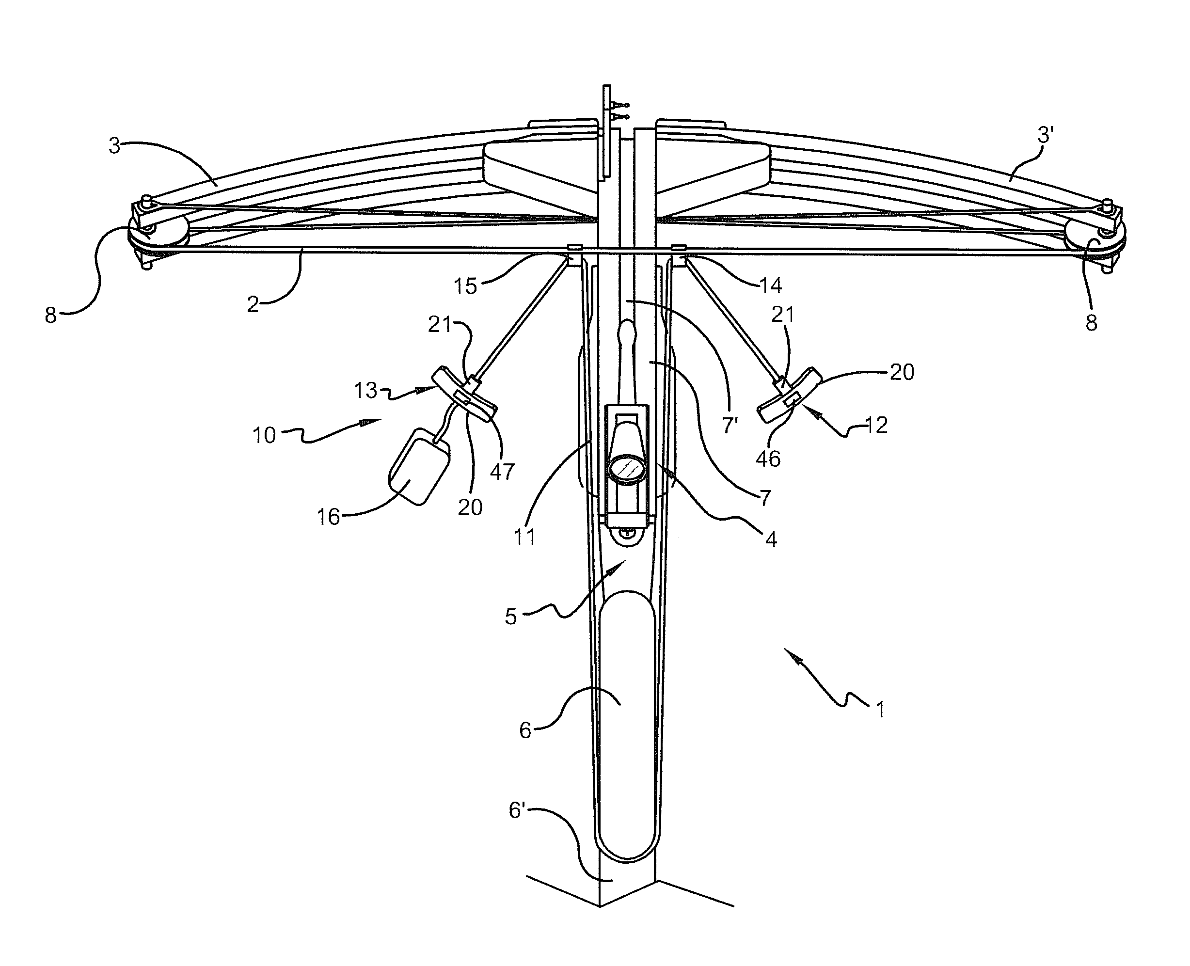
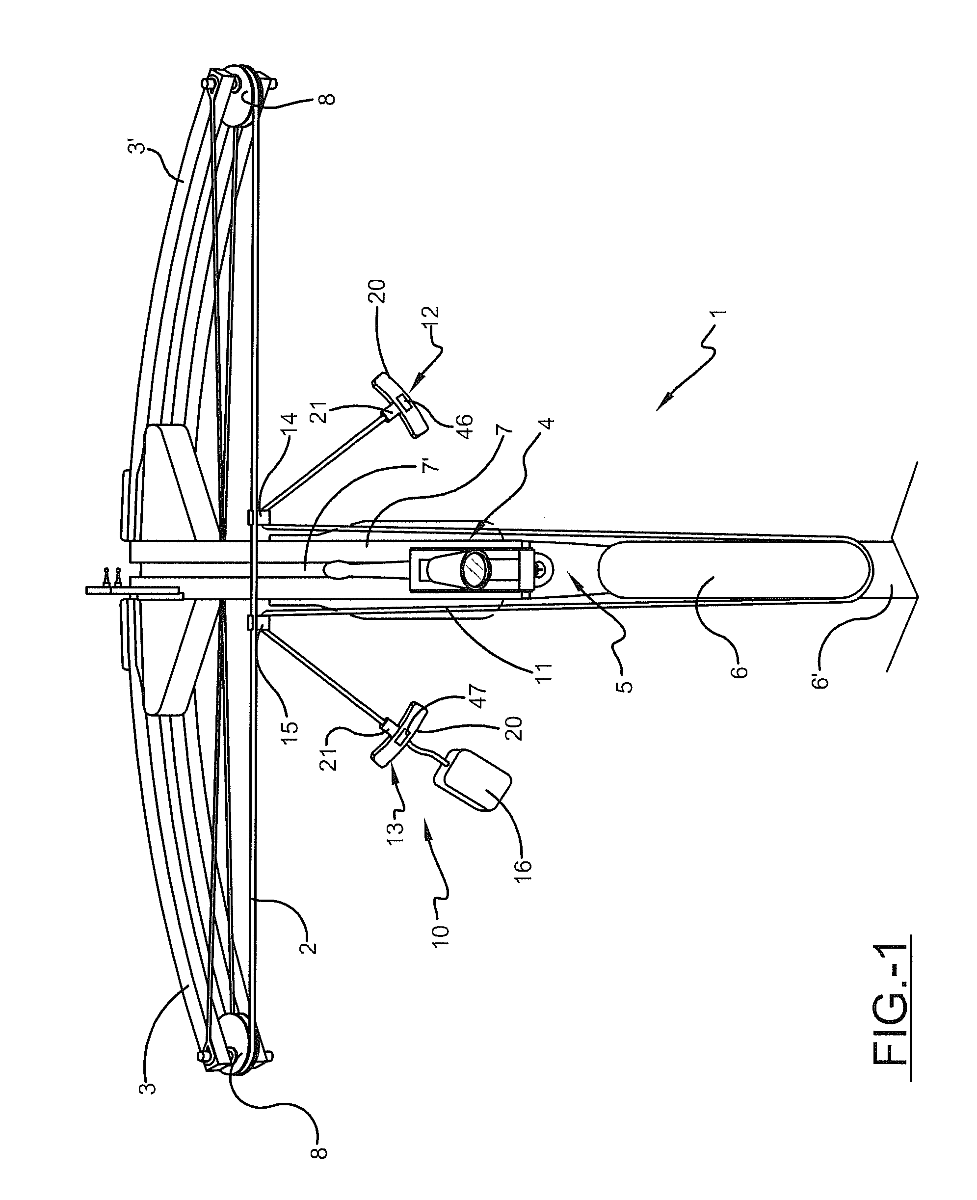
[0032]In either of a first or second embodiment, the first and second handles 12, 13 or 12, 13′ may comprise first and second magnets 46, 47, respectively. The first and second magnets 46, 47 may comprise conventional magnets having a pair of oppositely charged poles and may be positioned within or coupled to the first and second handles 12, 13 or 12, 13′. The first and second magnets 46, 47 may be positioned within the first and second handles 12, 13 or 12, 13′ such that when proximately located the first and second magnets 46, 47 may urge the first and second handles 12, 13 or 12, 13′ into contact with each other. In one embodiment, the first and second magnets 46, 47 may be positioned within or coupled to the first and second handles 12, 13 or 12, 13′ such that the poles of the first and second magnets 46, 47 extend along the longitudinal axis of the upper portion 20. In another embodiment, the first and second magnets 46, 47 may be positioned within or coupled to first and secon...

first embodiment

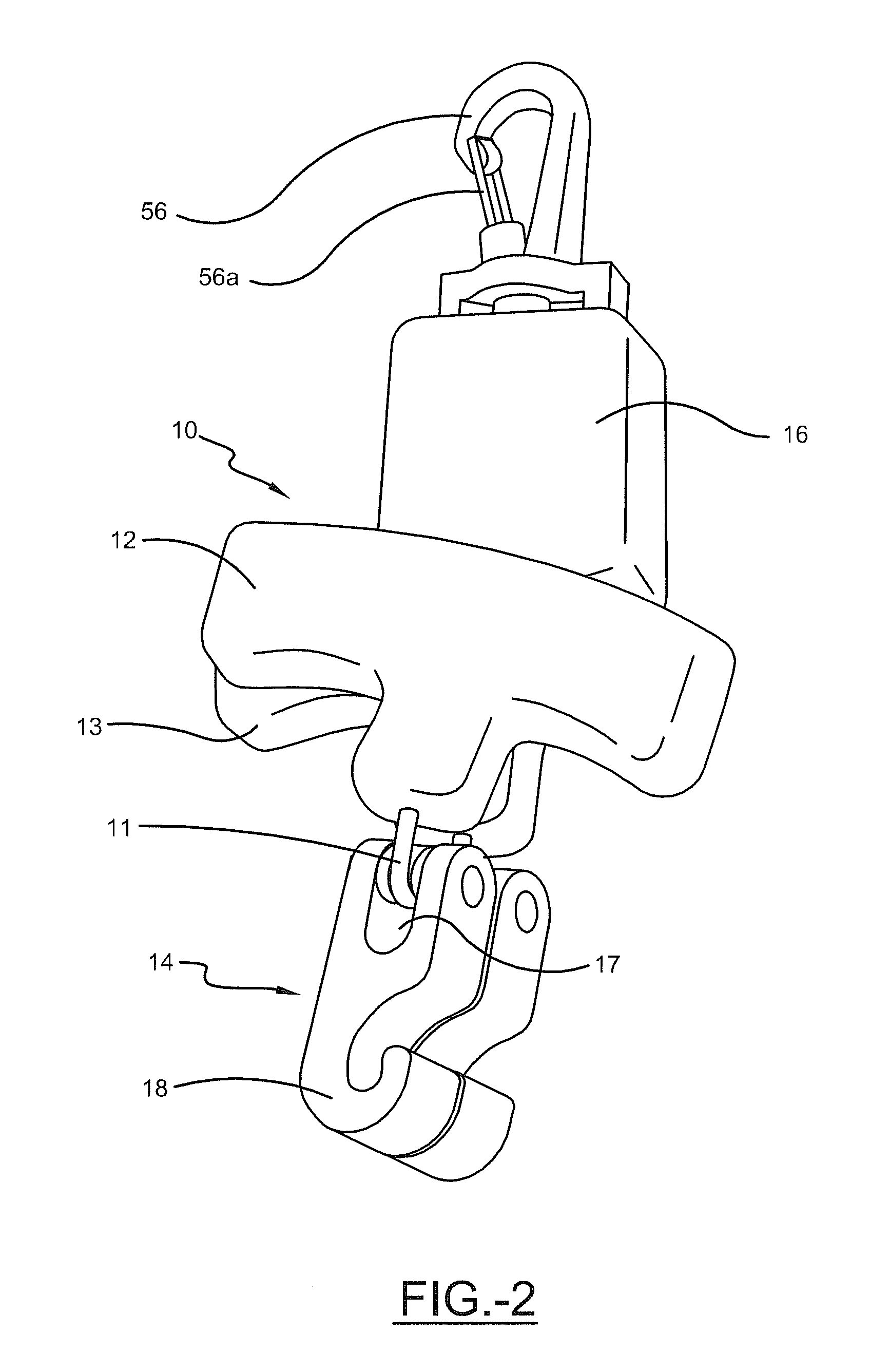
[0034]In a first embodiment, the flexible member may comprise a first end 11a fixedly attached to the first handle 12 and a second end 11b operatively connected to the housing 16. The second handle 13 and the first and second hook members 14, 15 may be slidably coupled to the flexible member 11 such that the first and second hook members 14, 15 are positioned between the first and second handles 12, 13. In one embodiment, the flexible member 11 may extend through a channel 48 formed through the second handle 13. The channel 48 may comprise a diameter suitable to receive the flexible member 11 such that the second handle 13 can slide substantially freely along at least a portion of the flexible member 11. The channel 48 may extend through the substantial center of the second handle 13 substantially along the longitudinal axis of the stem portion 21. The flexible member 11 may be slidably coupled to the first and second hook members 14, 15 such that the flexible member 11 extends thro...


PUM


Abstract

A portable device for drawing the bowstring of a crossbow. The cocking device may be designed to prevent the uneven drawing of the crossbow and may eliminate the complex installation process typically required to retro-fit an existing crossbow with known cocking devices.

Description

[0001]This application claims priority to provisional patent application Ser. No. 61 / 258,303 titled Portable Cocking Device, filed on Nov. 5, 2009, which is incorporated herein by reference.BACKGROUND[0002]A. Field of Invention[0003]This invention pertains to the art of methods and apparatuses of bowstring drawing devices and even more particularly, to the art of methods and apparatuses of portable cocking devices for drawing a bowstring of a crossbow.[0004]B. Description of the Related Art[0005]It is known to increase the speed and accuracy at which a projectile is propelled from an archery device is to increase the stiffness of the outwardly extending bow limbs. However, increasing the stiffness of the outwardly extending bow limbs results in an increase in the effort or force required when pulling or drawing the bowstring into position for firing. At some point, simply increasing the stiffness of the outwardly extending bow arms becomes counterproductive since users do not have t...

Claims


Application Information

Patent Timeline
IPC IPC(8): F41B5/18
CPCF41B5/12F41B5/1469
Inventor BEDNAR, RICHARD L.SHAFFER, MICHAEL J.HOUT, JACOB A.
Owner HUNTERS MFG CO INC
Features
  • Generate Ideas
  • Intellectual Property
  • Life Sciences
  • Materials
  • Tech Scout
  • Unparalleled Data Quality
  • Higher Quality Content
  • 60% Fewer Hallucinations
Learn More