Cutting machine for stone materials

a cutting machine and stone material technology, applied in metal working equipment, manufacturing tools, working accessories, etc., can solve problems such as pollution of the working environment, and achieve the effects of reducing materials used, reducing cost, and reducing weight of the expanded basin

Active Publication Date: 2011-09-29
CHERVON HK LTD WANCHAI
View PDF26 Cites 7 Cited by
  • Summary
  • Abstract
  • Description
  • Claims
  • Application Information

AI Technical Summary

Benefits of technology

[0008]Incorporating the above elements, the present invention may result in a water-retaining device with an upward slope angle arranged on the expanded basin, which can block splashed muddy water in a multi-directional manner during cutting operation, and at the same time does not influence the operation for cutting workpiece since the workpiece can automatically keep a distance when it touches the water-retaining device. It may also provide a first connection part and a second connection part arranged on the expanded basin which can be used for connecting with one of the frame and the basin respectively, such that the expanded basin is mounted fixedly and firmly. The first connection part may be substantially perpendicular to the second connection part, so that the frame and the basin respectively bear forces from the different directions of the expanded basin and the forces are uniform. Further, the second connection part or the first connection part may be moveable between the first position and the second position, and correspondingly the first connection part or the second connection part may be located on the frame or the basin connected therewith, which can block the splashed muddy water in multiple directions during a cutting operation. Finally, a hollow portion may be formed on the expanded basin by removing a portion of the material of the expanded basin and may be located within an area of orthographic projection of the water-retaining plate on the expanded basin, which can decrease weight of the expanded basin, reduce the materials used and diminish cost.

Problems solved by technology

Due to the limitation of assembled angle and size of the expanded basin, the ability to receive the splashed polluted water is poor, which results in pollution of the working environment.

Method used


Image

  • Cutting machine for stone materials
  • Cutting machine for stone materials
  • Cutting machine for stone materials

Examples


Embodiment Construction

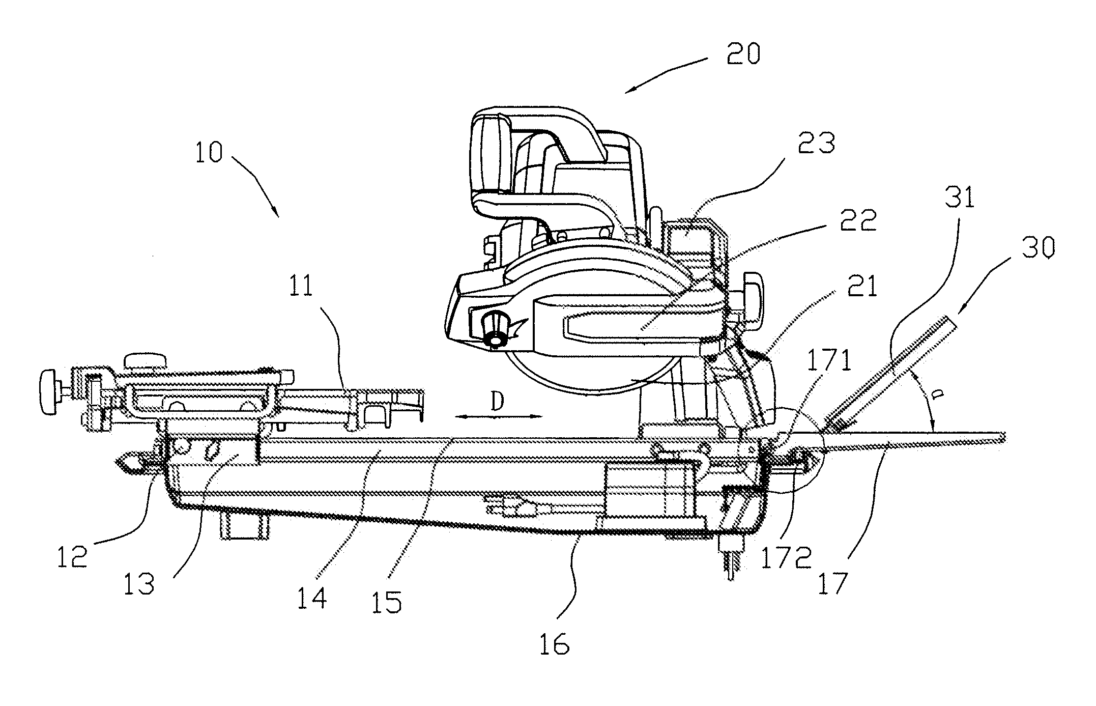
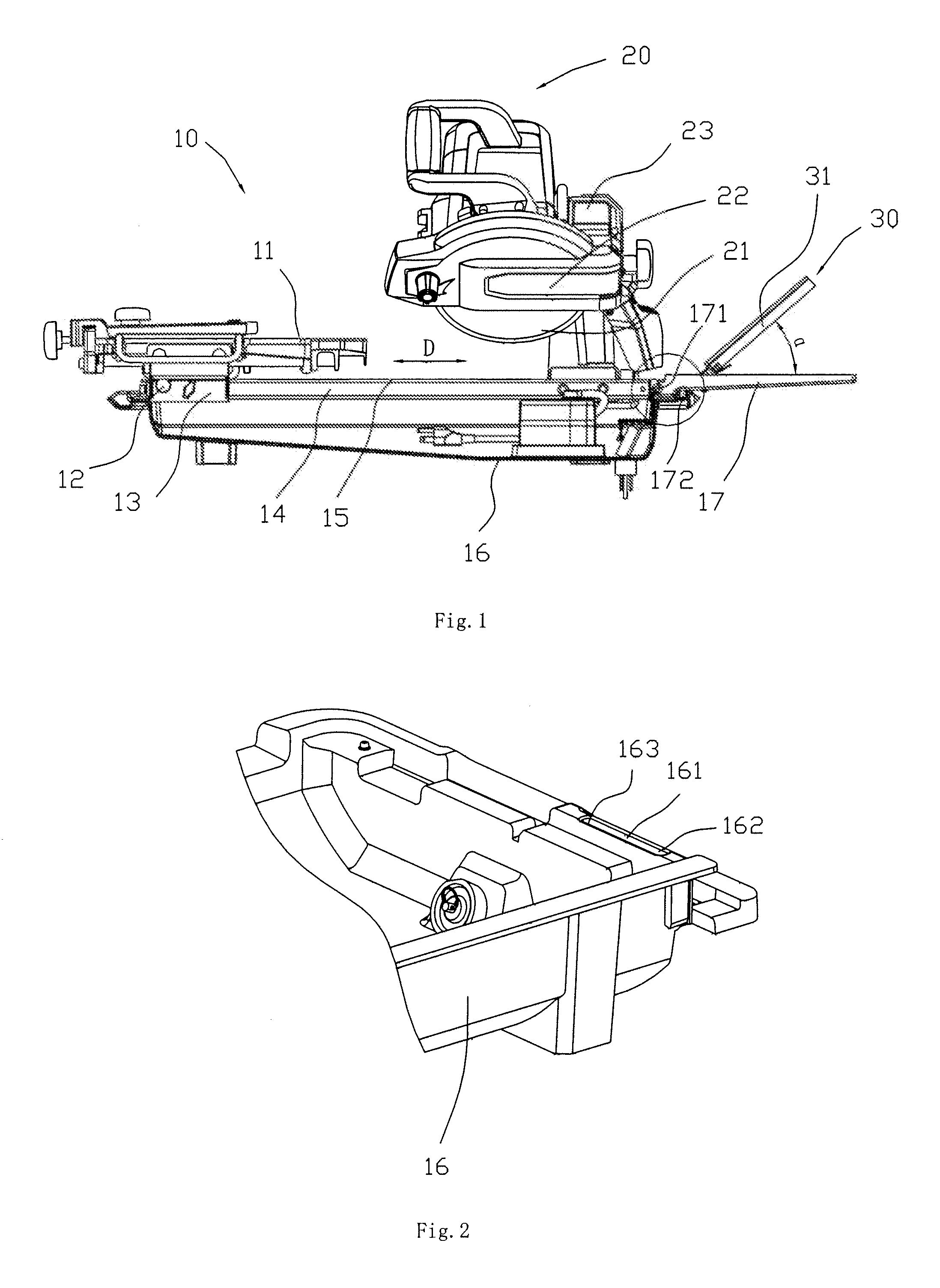
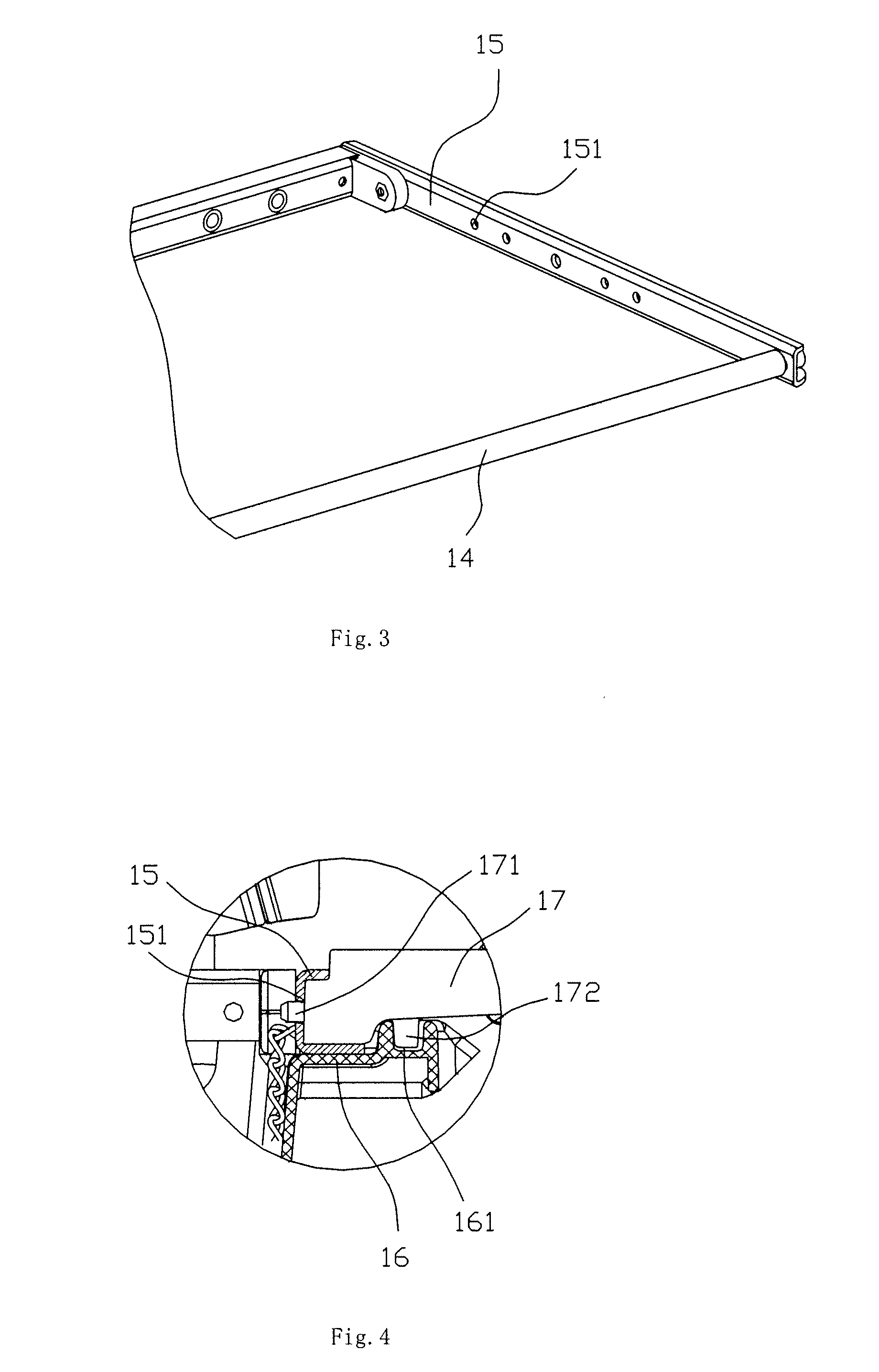
[0017]As shown in FIG. 1, it is a schematic view of the cutting machine for stone materials according to the present invention. The cutting machine 10 comprises a bedplate 11, a guide rail 14, a frame 15, a basin 16, an expanded basin 17 and a cutting device 20. The basin 16 is disposed under the frame 15 and serves as a support for the frame 15. Two sides of the frame 15 are respectively equipped with guide rails 14 parallel with each other. The bedplate 11 for supporting the work piece to be cut is disposed on the frame 15 and supported thereon. The bedplate 11 is mounted on the guide rails 14 so as to be slidable along the guide rails. The sliding direction thereof is shown as a double-headed arrow D in FIG. 1. The cutting device 20 is fixed to the guide rail on one side of the frame 15 via a supporting arm, and comprises a motor 23, a saw blade 21 and a saw blade protection device 22. The cutting function of the saw blade 21 can be implemented with the rotation of the saw blade ...


PUM

PropertyMeasurementUnit
slope angleaaaaaaaaaa
elasticaaaaaaaaaa
areaaaaaaaaaaa

Abstract

The present invention provides a cutting machine for stone materials having a power head part, a bedplate, a frame for supporting the bedplate and a basin disposed under the frame. The present invention may also have an expanded basin disposed outside of the basin and a water-retaining device with an upward slope angle may be arranged on the expanded basin to block splashed muddy water in a multi-directional manner during a cutting operation.

Description

CROSS-REFERENCE TO RELATED APPLICATIONS[0001]This application claims priority to CN 201020150067.0, filed Mar. 26, 2010, which is hereby incorporated by reference.FEDERALLY SPONSORED RESEARCH OR DEVELOPMENT[0002]Not Applicable.TECHNICAL FIELD[0003]The present invention relates to a cutting machine, more specifically to a cutting machine for cutting stone materials.BACKGROUND OF THE INVENTION[0004]Typically, a cutting machine for stone materials comprises a power head part, a bedplate, a frame for supporting the bedplate and a basin disposed under the frame. The frame is equipped with a guide rail for the bedplate to slide on. When performing a cutting operation, a work piece to be cut is placed on the bedplate and the bedplate is then moved toward the power head part to perform the cutting operation. The basin has a bottom surface and an upright wall around the periphery of the bottom surface, and receives water therein such that dust and noise pollution during the cutting operation...

Claims


Application Information

Patent Timeline
Patent Type & Authority Applications(United States)
IPC IPC(8): B28D7/02B28D1/04
CPCB28D7/02B28D1/047Y10T83/263
Inventor CAO, YANGGUAN, BANGLINWEI, HONGGE
Owner CHERVON HK LTD WANCHAI
Why Eureka
Try Eureka